CNC Machining Impeller
ABSTRACT
At the same time, this design for the manufacturing process of the impeller design and processing procedures, the immediate purpose is to introduce the details of the impeller manufacturing, the use of UG solve the problem in the manufacturing industry in the preparation of impeller machining program. Introduced the idea of impeller manufacturing method. Indirect purpose is to make the CNC machining better known, and let more people know the advantages of CNC machining, processing range.
Keywords: CNC machining; UG; tool path, machining simulation, three-dimensional solid modeling, processes; impeller
 1.1 Product Description
Integral impeller is a key component of power machinery, widely used in aerospace and other fields, and its processing technology has always been an important issue in manufacturing. From the overall impeller geometry and process can be seen: The machining trajectory planning has more constraints when machining an integral impeller. The space between adjacent vane is small and it is easy to produce collision interference during processing. It is difficult to automatically generate non-interfering machining trajectories. Therefore, in the process of machining the impeller, it is necessary not only to ensure that the machining trajectory of the vane surface can meet the requirements of geometric accuracy. And because the thickness of the vane is limited, Therefore, we must pay attention to trajectory planning in actual processing to maintain the quality of machining.
1.2 Selection of processing methods
Integral impeller machining has always been a difficult problem for engineers and technicians in mechanical processing. In order to process a qualified impeller, people have come up with many solutions. After forming from the initial casting light repair, afterwards paraffin wax casting, there are methods such as EDM. among them, some manufacturers use three-dimensional copy milling. However, these methods are not inefficient processing, precision is poor or the mechanical properties of the product, Until the application of CNC machining technology to the processing of impellers, these problems have been fundamentally resolved.
The complexity of impeller machining lies mainly in the fact that its vane are complex curved surfaces. And whether it can accurately machine impellers with complex shapes has become an important standard for measuring the performance of CNC machine tools. As CNC machine tools have four-axis linkage or five-axis linkage,
When using it for impeller machining, it can ensure that the ball head part of the tool can accurately cut the workpiece. It can also use its rotating shaft to make the tool body or tool bar part avoid the other parts of the workpiece to avoid interference or over-cutting.
Chapter 2 Three-dimensional solid modeling of integral impeller
2.1 Overview of modeling methods
2.1.1 General modeling methods
There are three application types for surface modeling:
(1) original product design, creating a surface model from a sketch;
(2) According to the two-dimensional drawings for surface modeling, the so-called drawing modeling;
(3) reverse engineering, that point mapping modeling.
This time introduce the second type of general implementation steps. The drawing process can be divided into two stages.
The first stage is modeling analysis to determine the correct modeling ideas and methods. include:
(1) on the basis of the product recognized correctly FIG decomposed into a single curved surface or face group.
(2) Determine the type and generation method of each surface, such as ruled surface, draft surface, or scavenging surface;
(3) determining the relationship between the connect surfaces (such as chamfering, cutting, etc.) and a connect sequence.
The second stage is the realization of modeling, including:
(1) According to the drawing, draw the necessary 2D view contour line in the CAD/CAM software and transform each view to the actual position of the space.
(2) For each type of surface, use the contour lines in each view to complete the modeling of each surface;
(3) Complete chamfering, cutting, etc. based on the connection relationship between surfaces;
(4) Complete the modeling of the structure (entity) in the product.
2.1.2 Method of Modeling Impeller
The solid shape of the overall impeller was created, mainly consisting of two parts: the vane and the hub. The curved surface of the vane is a free surface with high requirements for smoothness and continuity. The section line is a complex free curve, so the shape of the vane is difficult to model. At present, the section line is generally created first, and then the surface of the vane is modeled by means of the section line. The creation of the wheel boss is relatively simple. Create a section line string in sketch mode. Stretch the section line string with the stretch command to create the wheel boss. Rotary commands can also be used to model the wheel boss. It can be seen that the key to the overall impeller shape is the shape of the vane body. The solid shape of the vane is a key part of the overall impeller modeling work. Its design requirements are high and the surface features are also more complex.
2.2 The creation of wheel boss
The creation of the wheel boss is relatively simple, there are two ways to choose, one is to carry out three-dimensional modeling directly, the other is to create a sketch and then stretch. The second method is used to create the section line string in the sketch mode, and then use the stretching command to rotate the section line string to create the wheel boss, as shown in Figure 2-1 and 2-2.
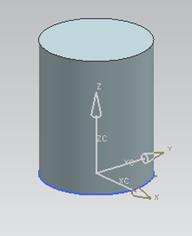
Figure 2-1 Hub Sketch Figure 2-2 Wheel Hub
2.3 The creation of vane
Make a vane sketch curve and generate a single vane, as shown in Figures 2-3, 2-4.
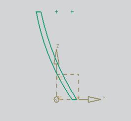
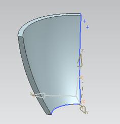
Figure 2-3 Vane plane projection Figure 2-4 Vane entity
By transforming commands, other vanes are generated, as shown in Figure 2-5 and Figure 2-6.
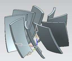
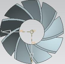
Figure 2-5 Rotating vane Figure 2-6 Top view of rotating vane
2.4 Impeller Generation
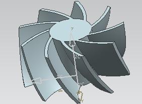
Connect the vane and wheel boss together by the sum command. As shown in Figure 2-7, 2-8.

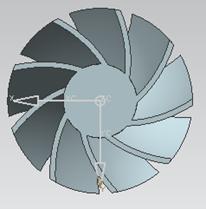
Figure 2-7 Solid body of impeller Figure 2-8 Solid body of impeller
Make center hole and keyway, and add chamfer at the junction of vane and wheel boss, as shown in Figure 2-9, 2-10.
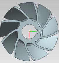
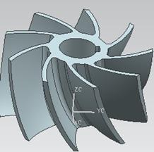
Fig. 2-9 Completion of impeller modeling Fig. 2-10 Top view of impeller
The impeller material should have good comprehensive mechanical properties, and the room temperature and high temperature strength, plasticity, and toughness all have high requirements. For this reason, the impeller must meet sufficient requirements:
(1) adequate room temperature, high temperature mechanical properties;
(2) have a high vibration damping capacity;
(3) High organizational stability;
(4) good corrosion and erosion resistance capability;
(5) Good process performance.
Because the impeller is one of the key components of the aeroengine, its requirement for materials is to minimize the weight of the parts while ensuring that the parts have sufficient strength. Opt for the grades of LD5 aluminum alloy after considering the usability and manufacturability of the part.
The integral impeller is a center symmetrical part, and the impeller must be accurately positioned during machining. Select the positioning reference: hole + surface, using the short plane of the outlet end as the axial positioning reference, use the center hole of the impeller as the axial positioning reference. When machining integral impeller, the impeller jig blank mounted on a mandrel and then pressed against the upper and lower ends.
3.2 Formulation of process routes
Taking into account the actual work of the whole impeller, generally, the overall surface of the impeller has high precision, high-speed rotation during work, and demands for dynamic balance are high. Combined with the impeller's shape, structural characteristics, material impeller processing characteristics analysis:
(1) There are many vanes on the impeller. The vane varies according to the diameter of the wheel boss. Vane has a long and short, vane is a curved surface, a high degree of distortion, and an elevation angle, the relative motion of the tool during machining can easily cause interference on adjacent vanes, so the choice of tool cutting direction is especially important. In addition, the curved surface needs to be processed in sections, and care should be taken to ensure the consistency of the surface to be machined.
(2) The flow path between vane is relatively narrow, the processing space is small, it is difficult to use large-diameter tools with good strength and rigidity;
(3) The radius of radius curvature of vane inlet and outlet edges changes greatly, which greatly changes the angle of tool and fixture;
(4) In order to meet the strength requirements, the transition between impeller wheel boss and vane adopts the smoothing method, and should pay great attention to the selection of the tool;
(5) Vane is a thin-walled part with a complex structure and poor process rigidity. Process arrangements need to consider multiple steps to repeatedly process the vane profile to prevent deformation due to machining residual stresses;
(6) The material of the overall impeller is generally aluminum alloy, stainless steel, titanium alloy, etc. Therefore, in order to improve the overall impeller strength, Blanks generally use forgings, and then the reference plane turning, machining the basic shape of the impeller gyrator.
Arrange the tool path as follows:
1, truning cylindrical;
2, milling end surface;
3, drilling center hole;
4, bore a hole;
5, plug keyway;
6, roughing impeller contour;
7, rough processing vane;
8, rough processing;
9, finishing vane;
10, finishing flow surface;
11, grinding edge deburring.
4.2 Creating a Processing Environment
UG can choose a variety of processing methods, there are for general processing, there are for multi-axis machining, impeller machining for more than three-axis multi-axis machining, so the ordinary processing methods can not meet the impeller processing, so determine the processing environment for Variable contour milling, as shown in Figure 4-2, 4-3
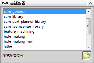
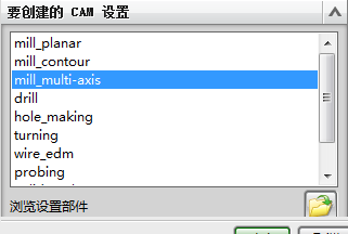
Figure 4-2 CAM configuration Figure 4-3 Processing environment
4.4 Processing parameter setting and generation of cutting path
4.4.1 Tool Trajectory Planning Method
The purpose of the tool path planning is to generate a set of tool positions for the parts to be machined, so that the machining efficiency is highest under the premise of ensuring the machining accuracy. For the two-axis and three-axis NC machining tool trajectory planning, the planning process can be regarded as the process of determining the X, Y axis coordinates of the tool location. At the same time, the initial value of the Z-axis coordinate can be determined. Then the interference-free calculation of the Z axis coordinate is completed by the subsequent interference process. For the five-axis surface machining tool trajectory planning, the initial position of the tool axis vector is parallel to the normal vector at the tool location point. The planning process also includes determining the rotation angle of the cutter axis vector around the maximum principal curvature at the knife location, ie, the heel angle. And the angle of rotation around the direction of vectoring, ie, the angle of side slip, these two angles together determine the spatial attitude of the tool.
The tasks of tool path planning can be summarized as follows:
(1) determining the geometry of the tool trajectory;
(2) Determine the connection sequence and connection method of the tool trajectory line;
(3) Determine the density of the tool trajectory line and the density of the tool location on the tool trajectory;
(4) In tool path planning for five-axis NC machining, the tool space attitude at each tool location must also be determined.
Multi-axis NC tool trajectory generation is the basis and key of NC programming. There are many different calculation methods for different machining objects. Some workpiece surfaces can be completed in a single pass, as long as the optimal direction of the pass can be determined. Some need more than one pass to complete, which will produce multiple tool paths.
4.4.3 Process Simulation
After all the cutting paths are set, 3D simulation is performed and post-processing is performed. After-treatment selects 4-axis machining.
Simulation results, as shown in Figure 4-20, 4-21, 4-22
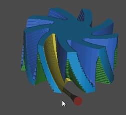
Figure 4-20 Contour simulation results
4.5 post processing
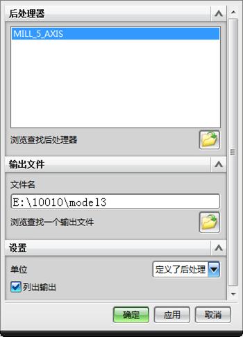
NC programming post-processing includes the generation of machining tool path files and the generation of machine tool NC code instruction sets. The post-processor reads the tool path file generated by the system, extracts relevant machining information from it, and analyzes, judges, and processes the specified NC machine tool according to the characteristics and NC program format requirements. Finally generate NC programs directly recognizable by CNC machines. It is the post processing of CNC machining. It directly affects the use of CAD/CAM software and the machining quality of parts. Select the 5-axis machining and export the NC program, as shown in Figure 4-23.
4.6 Machine Simulation
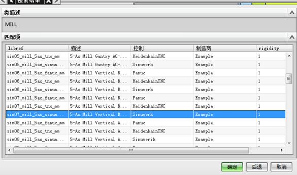
The machine uses a five-axis vertical milling machine and the control system is Sinumerk. If there is no selected machine model and control system in the UG post-processing module, the post-processing constructor in the processing tool must be selected through the UG start menu. The post-processing constructor is to generate post-processing files by setting the selected machine tool's processing parameters and detailed parameters of the control system, and then through the UG processing module, select the corresponding program, select post-processing, and a post-processing dialog box will appear. There is a default post-processing file in the dialog box. You can also select the post-processing file you have created, and then select the location and unit to save.
The choice of machine tool, as shown in Figure 4-24
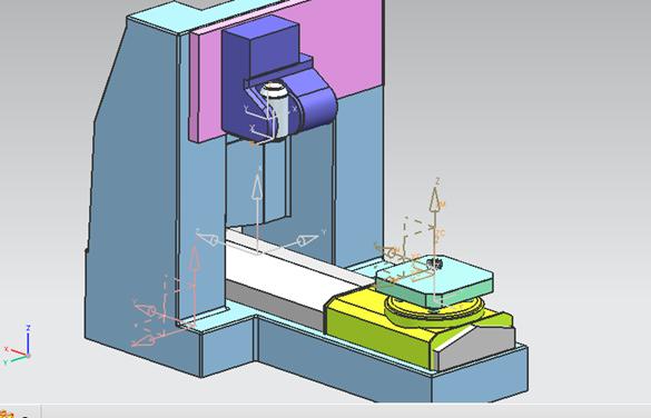
Figure 4-24 Machine Tool Selection
UG can directly call the generated program block from the simulation module to process. In the simulation interface, you can see the machine tool speed, feed rate and coolant status. You can also monitor the coordinates of the tool in real time. In the NC program area, you can see The current processing stage of the program code. As shown in Figure 4-25.
Chapter 5 Summary
The main work of this design was the numerical control of the impeller and the simulation of the machine tool. From the selection of the part to the final simulation of the virtual machine tool, it experienced a lot of failures. After the improvement, the design was finally completed.Five-axis CNC machining is one of the better solutions for obtaining complex surfaces and irregular parts, especially those curves and surfaces that are described by certain numerical theoretical equations and require sufficient accuracy, such as the overall impeller vane, and at the same time, The development and application of coordinate processing technology is closely related to CAD/CAM technology. This design mainly uses the aero-engine monolithic impeller as an example, and analyzes and studies its geometric modeling, tool position calculation, tool path planning, and numerical control processing technology.
At the same time, this design for the manufacturing process of the impeller design and processing procedures, the immediate purpose is to introduce the details of the impeller manufacturing, the use of UG solve the problem in the manufacturing industry in the preparation of impeller machining program. Introduced the idea of impeller manufacturing method. Indirect purpose is to make the CNC machining better known, and let more people know the advantages of CNC machining, processing range.
Keywords: CNC machining; UG; tool path, machining simulation, three-dimensional solid modeling, processes; impeller
Integral impeller is a key component of power machinery, widely used in aerospace and other fields, and its processing technology has always been an important issue in manufacturing. From the overall impeller geometry and process can be seen: The machining trajectory planning has more constraints when machining an integral impeller. The space between adjacent vane is small and it is easy to produce collision interference during processing. It is difficult to automatically generate non-interfering machining trajectories. Therefore, in the process of machining the impeller, it is necessary not only to ensure that the machining trajectory of the vane surface can meet the requirements of geometric accuracy. And because the thickness of the vane is limited, Therefore, we must pay attention to trajectory planning in actual processing to maintain the quality of machining.
1.2 Selection of processing methods
Integral impeller machining has always been a difficult problem for engineers and technicians in mechanical processing. In order to process a qualified impeller, people have come up with many solutions. After forming from the initial casting light repair, afterwards paraffin wax casting, there are methods such as EDM. among them, some manufacturers use three-dimensional copy milling. However, these methods are not inefficient processing, precision is poor or the mechanical properties of the product, Until the application of CNC machining technology to the processing of impellers, these problems have been fundamentally resolved.
The complexity of impeller machining lies mainly in the fact that its vane are complex curved surfaces. And whether it can accurately machine impellers with complex shapes has become an important standard for measuring the performance of CNC machine tools. As CNC machine tools have four-axis linkage or five-axis linkage,
When using it for impeller machining, it can ensure that the ball head part of the tool can accurately cut the workpiece. It can also use its rotating shaft to make the tool body or tool bar part avoid the other parts of the workpiece to avoid interference or over-cutting.
Chapter 2 Three-dimensional solid modeling of integral impeller
2.1.1 General modeling methods
There are three application types for surface modeling:
(1) original product design, creating a surface model from a sketch;
(2) According to the two-dimensional drawings for surface modeling, the so-called drawing modeling;
(3) reverse engineering, that point mapping modeling.
This time introduce the second type of general implementation steps. The drawing process can be divided into two stages.
The first stage is modeling analysis to determine the correct modeling ideas and methods. include:
(1) on the basis of the product recognized correctly FIG decomposed into a single curved surface or face group.
(2) Determine the type and generation method of each surface, such as ruled surface, draft surface, or scavenging surface;
(3) determining the relationship between the connect surfaces (such as chamfering, cutting, etc.) and a connect sequence.
The second stage is the realization of modeling, including:
(1) According to the drawing, draw the necessary 2D view contour line in the CAD/CAM software and transform each view to the actual position of the space.
(2) For each type of surface, use the contour lines in each view to complete the modeling of each surface;
(3) Complete chamfering, cutting, etc. based on the connection relationship between surfaces;
(4) Complete the modeling of the structure (entity) in the product.
2.1.2 Method of Modeling Impeller
The solid shape of the overall impeller was created, mainly consisting of two parts: the vane and the hub. The curved surface of the vane is a free surface with high requirements for smoothness and continuity. The section line is a complex free curve, so the shape of the vane is difficult to model. At present, the section line is generally created first, and then the surface of the vane is modeled by means of the section line. The creation of the wheel boss is relatively simple. Create a section line string in sketch mode. Stretch the section line string with the stretch command to create the wheel boss. Rotary commands can also be used to model the wheel boss. It can be seen that the key to the overall impeller shape is the shape of the vane body. The solid shape of the vane is a key part of the overall impeller modeling work. Its design requirements are high and the surface features are also more complex.
2.2 The creation of wheel boss
The creation of the wheel boss is relatively simple, there are two ways to choose, one is to carry out three-dimensional modeling directly, the other is to create a sketch and then stretch. The second method is used to create the section line string in the sketch mode, and then use the stretching command to rotate the section line string to create the wheel boss, as shown in Figure 2-1 and 2-2.
Figure 2-1 Hub Sketch Figure 2-2 Wheel Hub
2.3 The creation of vane
Make a vane sketch curve and generate a single vane, as shown in Figures 2-3, 2-4.
Figure 2-3 Vane plane projection Figure 2-4 Vane entity
By transforming commands, other vanes are generated, as shown in Figure 2-5 and Figure 2-6.
Figure 2-5 Rotating vane Figure 2-6 Top view of rotating vane
2.4 Impeller Generation
Connect the vane and wheel boss together by the sum command. As shown in Figure 2-7, 2-8.
Figure 2-7 Solid body of impeller Figure 2-8 Solid body of impeller
Make center hole and keyway, and add chamfer at the junction of vane and wheel boss, as shown in Figure 2-9, 2-10.
Fig. 2-9 Completion of impeller modeling Fig. 2-10 Top view of impeller
Chapter 3 Impeller Processing Technology Analysis
3.1 The choice of materialsThe impeller material should have good comprehensive mechanical properties, and the room temperature and high temperature strength, plasticity, and toughness all have high requirements. For this reason, the impeller must meet sufficient requirements:
(1) adequate room temperature, high temperature mechanical properties;
(2) have a high vibration damping capacity;
(3) High organizational stability;
(4) good corrosion and erosion resistance capability;
(5) Good process performance.
Because the impeller is one of the key components of the aeroengine, its requirement for materials is to minimize the weight of the parts while ensuring that the parts have sufficient strength. Opt for the grades of LD5 aluminum alloy after considering the usability and manufacturability of the part.
The integral impeller is a center symmetrical part, and the impeller must be accurately positioned during machining. Select the positioning reference: hole + surface, using the short plane of the outlet end as the axial positioning reference, use the center hole of the impeller as the axial positioning reference. When machining integral impeller, the impeller jig blank mounted on a mandrel and then pressed against the upper and lower ends.
3.2 Formulation of process routes
Taking into account the actual work of the whole impeller, generally, the overall surface of the impeller has high precision, high-speed rotation during work, and demands for dynamic balance are high. Combined with the impeller's shape, structural characteristics, material impeller processing characteristics analysis:
(1) There are many vanes on the impeller. The vane varies according to the diameter of the wheel boss. Vane has a long and short, vane is a curved surface, a high degree of distortion, and an elevation angle, the relative motion of the tool during machining can easily cause interference on adjacent vanes, so the choice of tool cutting direction is especially important. In addition, the curved surface needs to be processed in sections, and care should be taken to ensure the consistency of the surface to be machined.
(2) The flow path between vane is relatively narrow, the processing space is small, it is difficult to use large-diameter tools with good strength and rigidity;
(3) The radius of radius curvature of vane inlet and outlet edges changes greatly, which greatly changes the angle of tool and fixture;
(4) In order to meet the strength requirements, the transition between impeller wheel boss and vane adopts the smoothing method, and should pay great attention to the selection of the tool;
(5) Vane is a thin-walled part with a complex structure and poor process rigidity. Process arrangements need to consider multiple steps to repeatedly process the vane profile to prevent deformation due to machining residual stresses;
(6) The material of the overall impeller is generally aluminum alloy, stainless steel, titanium alloy, etc. Therefore, in order to improve the overall impeller strength, Blanks generally use forgings, and then the reference plane turning, machining the basic shape of the impeller gyrator.
Arrange the tool path as follows:
1, truning cylindrical;
2, milling end surface;
3, drilling center hole;
4, bore a hole;
5, plug keyway;
6, roughing impeller contour;
7, rough processing vane;
8, rough processing;
9, finishing vane;
10, finishing flow surface;
11, grinding edge deburring.
4.2 Creating a Processing Environment
UG can choose a variety of processing methods, there are for general processing, there are for multi-axis machining, impeller machining for more than three-axis multi-axis machining, so the ordinary processing methods can not meet the impeller processing, so determine the processing environment for Variable contour milling, as shown in Figure 4-2, 4-3
Figure 4-2 CAM configuration Figure 4-3 Processing environment
4.4 Processing parameter setting and generation of cutting path
4.4.1 Tool Trajectory Planning Method
The purpose of the tool path planning is to generate a set of tool positions for the parts to be machined, so that the machining efficiency is highest under the premise of ensuring the machining accuracy. For the two-axis and three-axis NC machining tool trajectory planning, the planning process can be regarded as the process of determining the X, Y axis coordinates of the tool location. At the same time, the initial value of the Z-axis coordinate can be determined. Then the interference-free calculation of the Z axis coordinate is completed by the subsequent interference process. For the five-axis surface machining tool trajectory planning, the initial position of the tool axis vector is parallel to the normal vector at the tool location point. The planning process also includes determining the rotation angle of the cutter axis vector around the maximum principal curvature at the knife location, ie, the heel angle. And the angle of rotation around the direction of vectoring, ie, the angle of side slip, these two angles together determine the spatial attitude of the tool.
The tasks of tool path planning can be summarized as follows:
(1) determining the geometry of the tool trajectory;
(2) Determine the connection sequence and connection method of the tool trajectory line;
(3) Determine the density of the tool trajectory line and the density of the tool location on the tool trajectory;
(4) In tool path planning for five-axis NC machining, the tool space attitude at each tool location must also be determined.
Multi-axis NC tool trajectory generation is the basis and key of NC programming. There are many different calculation methods for different machining objects. Some workpiece surfaces can be completed in a single pass, as long as the optimal direction of the pass can be determined. Some need more than one pass to complete, which will produce multiple tool paths.
4.4.3 Process Simulation
After all the cutting paths are set, 3D simulation is performed and post-processing is performed. After-treatment selects 4-axis machining.
Simulation results, as shown in Figure 4-20, 4-21, 4-22
Figure 4-20 Contour simulation results
4.5 post processing
NC programming post-processing includes the generation of machining tool path files and the generation of machine tool NC code instruction sets. The post-processor reads the tool path file generated by the system, extracts relevant machining information from it, and analyzes, judges, and processes the specified NC machine tool according to the characteristics and NC program format requirements. Finally generate NC programs directly recognizable by CNC machines. It is the post processing of CNC machining. It directly affects the use of CAD/CAM software and the machining quality of parts. Select the 5-axis machining and export the NC program, as shown in Figure 4-23.
4.6 Machine Simulation
The machine uses a five-axis vertical milling machine and the control system is Sinumerk. If there is no selected machine model and control system in the UG post-processing module, the post-processing constructor in the processing tool must be selected through the UG start menu. The post-processing constructor is to generate post-processing files by setting the selected machine tool's processing parameters and detailed parameters of the control system, and then through the UG processing module, select the corresponding program, select post-processing, and a post-processing dialog box will appear. There is a default post-processing file in the dialog box. You can also select the post-processing file you have created, and then select the location and unit to save.
The choice of machine tool, as shown in Figure 4-24
Figure 4-24 Machine Tool Selection
UG can directly call the generated program block from the simulation module to process. In the simulation interface, you can see the machine tool speed, feed rate and coolant status. You can also monitor the coordinates of the tool in real time. In the NC program area, you can see The current processing stage of the program code. As shown in Figure 4-25.
Chapter 5 Summary


