On the Influence of Turning Tool Geometric Parameters on Machining Accuracy of CNC Lathe
【Abstract】 With the development of industrial technology, the application of CNC lathes in industrial processing has become more and more widespread. In the numerical control machining process, the geometric parameters such as the arc radius r of the tool tip, the main declination angle kr, and the deviation of the tool tip from the height of the center of the part are generally investigated. In order to improve the smoothness of the workpiece surface and reduce tool wear, it is easy to control the cutting force of the tool. Tool geometry parameters affect the axial dimension error and longitudinal dimension error of the machined part, and the surface shape of the machined part also changes. This article focuses on the influence of the arc radius of the tool tip of the CNC lathe on the machining accuracy of the part and facilitates effective measures in the processing of the part.
【Keywords】 turning tool; geometric parameters; part machining; accuracy effect
In the machining process of CNC lathes, the quality of parts will be affected by many factors, such as the geometric parameters of the radius of the tool nose, the leading angle, etc. The geometric parameters will change during the use of the tool, affect the machining quality, dimensional accuracy and shape accuracy of the part, and accelerate the wear of the tool. Therefore, during the processing of parts, it is necessary to reasonably select the arc radius of the tool tip in combination with the actual part size, and to apply effective methods to improve the part's machining accuracy and processing quality.
1. The radius of the cutting edge arc affects the dimensional accuracy of cylindrical parts
The tangential point of contact between the turning tool and the surface of the machined part forms a complete surface. Figure 1 shows several common parts processing methods.
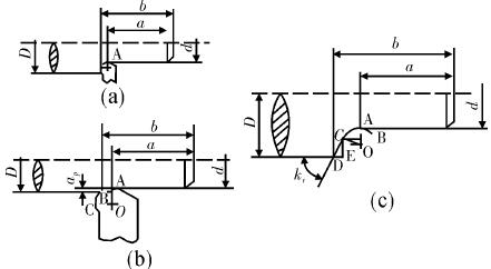 In the figure, A is the tip of the arc of the tip. When the leading angle kr is 90°, the tip A of the arc of the tip can meet the accuracy requirement of the axial dimension of the machined part. As (a) shows, if (D - d) /2 = ap> r, the arc radius of the tool nose during machining will cause the axial dimension of the machined part to change, and the change amount will be denoted as Δa. Then △a = b - a = r, where a is the actual axial displacement of the tool, b is the axial dimension of the part being machined, and r is the arc radius of the nose of the turning tool.
In this case, a is the actual axial displacement of the tool. Its value is: a = b —— △a = b —— r.
FIG arcuate vertex A is the tip, when the main angle kr = 90 °, the apex A tip arc required to meet the precision machining of parts is axial dimension. As (a) shows, if (D - d) /2 = ap> r, the arc radius of the tool nose during machining will cause the axial dimension of the machined part to change, and the change amount will be denoted as Δa. Then △a = b - a = r, where a is the actual axial displacement of the tool, b is the axial dimension of the part being machined, and r is the arc radius of the nose of the turning tool. At this point, a is the actual axial displacement of the tool. Its value is a = b - △a = b - r.
If (D - d) /2 = ap < r, the arc portion of the nose will assume all the cutting forces, and the axial dimension change Δa and the actual displacement length a of the turning tool will be the same as in the previous calculation. In short, in the process of machining cylindrical parts, the arc radius of the turning point of the turning tool tool and the leading angle of the turning tool will have a greater impact on the axial dimension of the part being machined. In the process of increasing the arc radius of the tool nose, the larger the axial dimension change, and vice versa.
Therefore, in compiling the part program, we must pay attention to the change of the axial displacement size. However, the radius of the arc of the cutting edge and the angle of main deflection have no influence on the radial dimension accuracy of cylindrical parts.
2. The radius of the cutting edge arc affects the dimensional accuracy of single-section cone parts.
Figure 2 is a schematic diagram of the processing of a single-stage cone part.
In the processing of single-section cone parts, if the turning tool is located at the initial machining point, ie, the I position, The B' point on the arc of the tip will be tangential to the starting point of the small end of the vertebral body part. In software programming, the center point of the tool nose arc will be used as a reference, and the change in the axial dimension of the small end of the cone part will be recorded as. After the part is machined, the turning tool will stop at position II. The arc radius of the tool nose will be tangent to the cone part at point B. Therefore, if the actual displacement of the tool is a, the axial length of the vertebral body part.
Therefore, in the process of machining single-segment cone parts, it is necessary to focus on the size effect of the radius of the tool nose. In the process of changing the axial dimension and radial dimension of the vertebral body, the arc radius of the tool tip increases, and the axial dimension of the machined part also increases. As the radial dimension decreases, the arc radius of the tool tip decreases, the axial dimension of the machined part decreases, and the radial dimension increases; The cone angle of the vertebral body part increases, the variation of the axial dimension increases, the radial dimension decreases, the cone angle of the vertebral body part decreases, the axial dimension decreases, and the radial dimension increases.
3, The radius of the tool nose arc influences the surface size of the double-section external cone part
In the process of machining double-section external cone parts, the relative positions of the turning tool and the part are shown in Fig. 3.
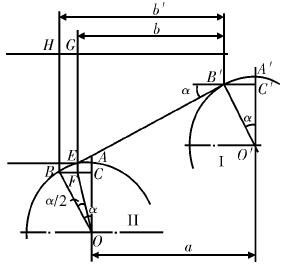
If the tool is in the initial machining position, it can be seen as a single vertebral body part machining, and the axial dimension changes similarly to the previous one. If the tool is in the position shown in Figure 3, it is at the end of the first single segment vertebral body processing and is also located at the initial processing position of the second segment of the vertebral body. In this case, the tip of the arc and the first segment of the vertebral body part, and the second segment of the vertebral body parts are tangent to point B and point E, respectively. In the figure, DBLEF is the theoretical trajectory, and the machined part is affected by the radius of the arc. The actual trajectory will change to DBL'EF, where the arc is mainly formed by the arc of tool nose.
Under the influence of the radius of the cutting edge arc, the axial dimension and the radial dimension of the processed two-part vertebral body parts will be affected. The axial dimension change of the first segment of the vertebral body is Δa1 = b1 - a1 = LC, since ∠BOH = α, ∠EOH = β, Therefore, ∠BOE = β - α, the tip of the arc and two parts of the vertebral body are tangent to the two points B, E, respectively, from the geometric relationship can be seen EL = BL, so ∠BOL = ∠EOL = (β - α) /2. In ∠BOL, there is BL = rtg[( β - α ) /2]. In ∠BCL there is LC = BLcosα = rcosαtg[( β - α ) / 2 ], the actual axial displacement of the turning tool The size is a1 = b1 - △a1 = b1 - rcosαtg [( β - α ) / 2 ], Among them, α and β indicate the slopes of the first and second vertebrae, respectively. At the same time, the size of the axial dimension of the second segment of the vertebral body can also be directly calculated. Δa2 = EG = rcosβtg[( β - α ) / 2 ], The actual axial displacement dimension of the part a2 = b2 - △a2 = b2 - rcosβtg [(β - α) / 2].
The maximum diameter of the first segment of the vertebral body at this time is dmax = d1 - △d1 = d1 - 2rsinαtg[( β - α ) / 2 ],
The radial variation of the small end of the second segment of the vertebral body is Δd2 = 2LG = 2 rsinβtg [( β - α /2 ]), and the minimum diameter of the second vertebral body is dmin = d2 + Δd2 = d2 + 2 rsinβtg [( β - - α) / 2].
From the above analysis, it can be seen that in the process of processing the double-section outer vertebral parts, the axial dimension of the parts will change due to the change in the size of the arc of the tip. As the radius of the tool tip arc increases, the axial dimension of the part increases, and the change in the axial dimension is affected by the difference in cone angle between the two cones, and the axial dimension increases as the cone angle increases. In the process of analyzing the radial dimension, when the arc of the tool tip increases, the radial dimension of the first end of the vertebral body decreases, and the radial dimension of the second end of the vertebral body increases. when the difference of vertebral cone angle increases, the radial size of the first segment of the vertebral body decreases, and the radial dimension of the second segment of the vertebral body increases.
4. The radius of the cutting edge arc affects the surface of spherical parts
Machining dimensions The relative positions of turning tools and machined parts are shown in Fig. 4.
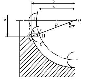
If the tool moves from the inside to the outside and the tool is in position I, the axial dimension of the part changes to Δa = b - a = r. When the non-integer hemispherical, the tool is in position Ⅱ, At this time, the point B arc of the tip is tangent to the spherical part. In this case, the dimension change of the part's axis is △a = b - a = EF = rsinα, where α represents the angle between the tool and the spherical part. At this time, the actual axial displacement of the tool can be expressed as: a = b - △ a = (R - r) sin α. In the process of machining the outer spherical surface, Δa takes a negative value.
During the processing of spherical parts, different points on the tool arc BC are cut in sequence, and the axial dimension change of the part is Δa = EF. When the big-end evaluation processing is performed after the spherical machining is completed, the tip of the arc of the tip is tangent to the end face of the part, and the axial dimension of the part becomes EF + AE. The radial dimension change Δd = 2BE = 2rcosα at this time, At this point the maximum diameter of the sphere becomes Dmax = D - △d = D - 2rcosα, and the axial dimension of the part changes from b to b' = b - AE. From the above analysis, it can be seen that during the processing of the spherical parts, the arc radius of the cutting edge affects the axial dimension of the part. As the arc radius of the tip increases, the axial dimension decreases, and the axial dimension decreases as the angle of the spherical surface increases.
5. Conclusion
The radius of the tool nose of the turning tool tool affects the machining accuracy of the part. In the process of machining the different shaped parts, attention must be paid to the control of the precision of the part. For example, in the software programming process, you can adjust the trajectory of the tool tip to ensure that the actual machining trajectory of the tool tip matches the ideal trajectory. The tool tip trajectory can be converted to the ideal tool nose trajectory by means of geometric calculations. The sketching, trajectory simulation, and programming steps are strictly followed in the programming process.
In addition, during the actual machining process, the arc radius r of the applied tool needs to be checked in time, and the influence of the arc radius of the tool tip is fully taken into account in the tool setting process. The tool compensation function of the CNC lathe system can be used to optimize the size.
【Keywords】 turning tool; geometric parameters; part machining; accuracy effect
In the machining process of CNC lathes, the quality of parts will be affected by many factors, such as the geometric parameters of the radius of the tool nose, the leading angle, etc. The geometric parameters will change during the use of the tool, affect the machining quality, dimensional accuracy and shape accuracy of the part, and accelerate the wear of the tool. Therefore, during the processing of parts, it is necessary to reasonably select the arc radius of the tool tip in combination with the actual part size, and to apply effective methods to improve the part's machining accuracy and processing quality.
1. The radius of the cutting edge arc affects the dimensional accuracy of cylindrical parts
The tangential point of contact between the turning tool and the surface of the machined part forms a complete surface. Figure 1 shows several common parts processing methods.
In this case, a is the actual axial displacement of the tool. Its value is: a = b —— △a = b —— r.
FIG arcuate vertex A is the tip, when the main angle kr = 90 °, the apex A tip arc required to meet the precision machining of parts is axial dimension. As (a) shows, if (D - d) /2 = ap> r, the arc radius of the tool nose during machining will cause the axial dimension of the machined part to change, and the change amount will be denoted as Δa. Then △a = b - a = r, where a is the actual axial displacement of the tool, b is the axial dimension of the part being machined, and r is the arc radius of the nose of the turning tool. At this point, a is the actual axial displacement of the tool. Its value is a = b - △a = b - r.
If (D - d) /2 = ap < r, the arc portion of the nose will assume all the cutting forces, and the axial dimension change Δa and the actual displacement length a of the turning tool will be the same as in the previous calculation. In short, in the process of machining cylindrical parts, the arc radius of the turning point of the turning tool tool and the leading angle of the turning tool will have a greater impact on the axial dimension of the part being machined. In the process of increasing the arc radius of the tool nose, the larger the axial dimension change, and vice versa.
Therefore, in compiling the part program, we must pay attention to the change of the axial displacement size. However, the radius of the arc of the cutting edge and the angle of main deflection have no influence on the radial dimension accuracy of cylindrical parts.
2. The radius of the cutting edge arc affects the dimensional accuracy of single-section cone parts.
Figure 2 is a schematic diagram of the processing of a single-stage cone part.
In the processing of single-section cone parts, if the turning tool is located at the initial machining point, ie, the I position, The B' point on the arc of the tip will be tangential to the starting point of the small end of the vertebral body part. In software programming, the center point of the tool nose arc will be used as a reference, and the change in the axial dimension of the small end of the cone part will be recorded as. After the part is machined, the turning tool will stop at position II. The arc radius of the tool nose will be tangent to the cone part at point B. Therefore, if the actual displacement of the tool is a, the axial length of the vertebral body part.
Therefore, in the process of machining single-segment cone parts, it is necessary to focus on the size effect of the radius of the tool nose. In the process of changing the axial dimension and radial dimension of the vertebral body, the arc radius of the tool tip increases, and the axial dimension of the machined part also increases. As the radial dimension decreases, the arc radius of the tool tip decreases, the axial dimension of the machined part decreases, and the radial dimension increases; The cone angle of the vertebral body part increases, the variation of the axial dimension increases, the radial dimension decreases, the cone angle of the vertebral body part decreases, the axial dimension decreases, and the radial dimension increases.
3, The radius of the tool nose arc influences the surface size of the double-section external cone part
In the process of machining double-section external cone parts, the relative positions of the turning tool and the part are shown in Fig. 3.
If the tool is in the initial machining position, it can be seen as a single vertebral body part machining, and the axial dimension changes similarly to the previous one. If the tool is in the position shown in Figure 3, it is at the end of the first single segment vertebral body processing and is also located at the initial processing position of the second segment of the vertebral body. In this case, the tip of the arc and the first segment of the vertebral body part, and the second segment of the vertebral body parts are tangent to point B and point E, respectively. In the figure, DBLEF is the theoretical trajectory, and the machined part is affected by the radius of the arc. The actual trajectory will change to DBL'EF, where the arc is mainly formed by the arc of tool nose.
Under the influence of the radius of the cutting edge arc, the axial dimension and the radial dimension of the processed two-part vertebral body parts will be affected. The axial dimension change of the first segment of the vertebral body is Δa1 = b1 - a1 = LC, since ∠BOH = α, ∠EOH = β, Therefore, ∠BOE = β - α, the tip of the arc and two parts of the vertebral body are tangent to the two points B, E, respectively, from the geometric relationship can be seen EL = BL, so ∠BOL = ∠EOL = (β - α) /2. In ∠BOL, there is BL = rtg[( β - α ) /2]. In ∠BCL there is LC = BLcosα = rcosαtg[( β - α ) / 2 ], the actual axial displacement of the turning tool The size is a1 = b1 - △a1 = b1 - rcosαtg [( β - α ) / 2 ], Among them, α and β indicate the slopes of the first and second vertebrae, respectively. At the same time, the size of the axial dimension of the second segment of the vertebral body can also be directly calculated. Δa2 = EG = rcosβtg[( β - α ) / 2 ], The actual axial displacement dimension of the part a2 = b2 - △a2 = b2 - rcosβtg [(β - α) / 2].
The maximum diameter of the first segment of the vertebral body at this time is dmax = d1 - △d1 = d1 - 2rsinαtg[( β - α ) / 2 ],
The radial variation of the small end of the second segment of the vertebral body is Δd2 = 2LG = 2 rsinβtg [( β - α /2 ]), and the minimum diameter of the second vertebral body is dmin = d2 + Δd2 = d2 + 2 rsinβtg [( β - - α) / 2].
From the above analysis, it can be seen that in the process of processing the double-section outer vertebral parts, the axial dimension of the parts will change due to the change in the size of the arc of the tip. As the radius of the tool tip arc increases, the axial dimension of the part increases, and the change in the axial dimension is affected by the difference in cone angle between the two cones, and the axial dimension increases as the cone angle increases. In the process of analyzing the radial dimension, when the arc of the tool tip increases, the radial dimension of the first end of the vertebral body decreases, and the radial dimension of the second end of the vertebral body increases. when the difference of vertebral cone angle increases, the radial size of the first segment of the vertebral body decreases, and the radial dimension of the second segment of the vertebral body increases.
4. The radius of the cutting edge arc affects the surface of spherical parts
Machining dimensions The relative positions of turning tools and machined parts are shown in Fig. 4.
If the tool moves from the inside to the outside and the tool is in position I, the axial dimension of the part changes to Δa = b - a = r. When the non-integer hemispherical, the tool is in position Ⅱ, At this time, the point B arc of the tip is tangent to the spherical part. In this case, the dimension change of the part's axis is △a = b - a = EF = rsinα, where α represents the angle between the tool and the spherical part. At this time, the actual axial displacement of the tool can be expressed as: a = b - △ a = (R - r) sin α. In the process of machining the outer spherical surface, Δa takes a negative value.
During the processing of spherical parts, different points on the tool arc BC are cut in sequence, and the axial dimension change of the part is Δa = EF. When the big-end evaluation processing is performed after the spherical machining is completed, the tip of the arc of the tip is tangent to the end face of the part, and the axial dimension of the part becomes EF + AE. The radial dimension change Δd = 2BE = 2rcosα at this time, At this point the maximum diameter of the sphere becomes Dmax = D - △d = D - 2rcosα, and the axial dimension of the part changes from b to b' = b - AE. From the above analysis, it can be seen that during the processing of the spherical parts, the arc radius of the cutting edge affects the axial dimension of the part. As the arc radius of the tip increases, the axial dimension decreases, and the axial dimension decreases as the angle of the spherical surface increases.
5. Conclusion
The radius of the tool nose of the turning tool tool affects the machining accuracy of the part. In the process of machining the different shaped parts, attention must be paid to the control of the precision of the part. For example, in the software programming process, you can adjust the trajectory of the tool tip to ensure that the actual machining trajectory of the tool tip matches the ideal trajectory. The tool tip trajectory can be converted to the ideal tool nose trajectory by means of geometric calculations. The sketching, trajectory simulation, and programming steps are strictly followed in the programming process.
In addition, during the actual machining process, the arc radius r of the applied tool needs to be checked in time, and the influence of the arc radius of the tool tip is fully taken into account in the tool setting process. The tool compensation function of the CNC lathe system can be used to optimize the size.


