Micro-mechanical Parts _ Micromachining of the Inner Surface Groove of the air Bearing Fine Copper, Titanium Tube
Key words: Micro mechanical parts, Micromachining of stainless steel parts, Miniature copper parts, Laser Lithography and Electrolytic Etching of Inner Surface of Aerostatic Bearing
Summary:
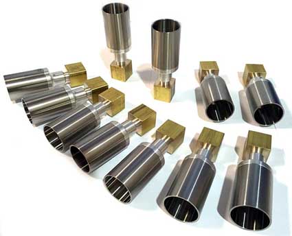
The application of laser scanning and photolithography technology on the inner surface of small diameter pipes has been studied in the processing of precise grooves of air bearings. Laser direct writing and lithography technology and subsequent electrolytic etching technology are used to precisely form a narrow band with a predetermined width of 28 microns on the surface of a copper tube with an inner diameter of 2 millimeters, thus creating a groove. The pipe is cut and manufactured into bearing bushing, and then the shaft with air bearing bushing is processed. A hollow aluminum alloy shaft is inserted therein, and the shaft is supported by air bearings and electromagnetic thrust bearings disposed at both ends. Then by blasting in the air, the shaft can rotate smoothly at high speeds in excess of 20,000 rpm. With conventional processing techniques, it is difficult to form precise elongated grooves on the inner surface of such a fine pipe. The results of the study show that the combination of lithography and etching techniques is very effective when processing micromechanical parts and requiring the formation of grooves on their inner surfaces.
1. Introduction
It is very difficult to machine fine textures or grooves on the inner surface of a small diameter pipe. Even if the mechanical tool can be placed inside the pipe and can be driven geometrically, the minimum inner diameter of the pipe is limited by the size of the tool and the shaft. In addition, because the shear force acts on the fine sample tube, they will deform, or the worktable supporting the sample tube will suddenly move, which needs to be considered in advance.
On the other hand, with laser scanning lithography, any fine resist pattern will be defined on the inner surface of the pipe having an inner diameter of less than 1 mm, and these pipes do not carry any external force. In addition, if the inner surface of the pipeline is marked with an anti-corrosion pattern and can be electrolytically etched appropriately, precise grooves will be obtained.
It is generally believed that the above-described internal etching techniques and electrolytic etching techniques can be used for the processing of grooves in bearings. In particular, the pair of diagonal parallel grooves known as "herringbone", we expect it to be suitable for high speed air bearings or hydrostatic bearings. In fact, the fine herringbone grooves on the inner surface of the 2 mm inner diameter copper pipe mentioned in this paper are processed in this way. In addition, the pipes are taken very short and then made into bushings. In addition, the pipes are intercepted very short and then made into bushings. The sleeve is fixed at the center of the shaft, and an aluminum hollow shaft is inserted therein. The aluminum hollow shaft and the holes in the pipe wall are supplied with air, and the shaft is supported by two pairs of herringbone bearings. The weight of the rotor is supported by several pairs of strong neodymium components. Therefore, when the air is blown in as the rotor driving force, the rotor smoothly rotates at a high rotational speed exceeding 20,000 rpm. The change and fluctuation of the rotational speed is much reduced compared to a rotor without an air bearing.
2. Photolithography on the inner surface of the fine tube
The principle of laser scanning and photolithography technology used on the surface of fine copper tube is shown in Fig. 1, and the manual exposure system for research is shown in Fig. 2. A semiconductor violet laser having a wavelength of 408 nm was used as an exposure light source (laser: TC20-405/20-4.5/15, and its model: DPS-5004). The emitted light was changed in shape by a pinhole having a diameter of 423 μm, and the image of the inner surface of the sample tube was magnified 20 times by using a combination of a 2x eyepiece and a 10x objective lens. At 45 degrees of the reflection rod inserted into the pipe from the other end, the laser beam is redirected, and then a circular spot having a diameter larger than 1/20 of the pinhole size is generated on the surface of the sample.
Using the reflected light from the illumination point, an image of the illumination spot on the sample tube is generated on the CCD camera, and the size and shape of the exposure spot are monitored before and during exposure. According to the program instructions, the pattern is defined by the automatic movement of the fine sample tube, which is clamped on the rotary table and the linear table. Tokyo Applied Chemistry Company uses positive P MER P-LA900PM as an anticorrosive agent, which is coated on the surface of the sample by an infective method. When the resist is exposed to a laser and the sample is immersed vertically into the developer PMER P-7G, the pattern is delineated. PMER P-7G is a special solution of 3% tetramethylammonium hydroxide (TMAH).
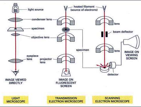
Figure 1 Principle of Scanning Exposure System on Fine Tube Surface
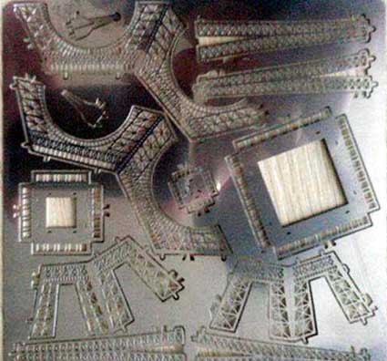
Figure 2 Handmade Exposure System for Research
3. Pipe internal etching
After the inner surface of the sample tube is processed with the resist pattern, etching occurs in the electrolytic etchant. The etchant is an aqueous solution containing sodium chloride, ammonium chloride and boric acid. Although the etching of the tube marked by the resist pattern from the outer surface can be successfully performed, it is difficult to apply etching from the inside using this technique. When etching occurs externally, the sample tube is placed as a sacrificial anode around a cylindrical aluminum cathode, as shown in FIG. On the other hand, in order to etch from the inside of the tube, it is necessary to understand the position where the cathode should be placed and how to connect the power supply line between the power source and the anode and cathode. However, Figure 4 shows a method that has been artificially designed after considerable research. In the present study, the sample tube was used as an anode, and an aluminum rod inserted therein was used as a cathode. According to the formula (1), when a voltage is applied to the anode copper tube, the copper atoms are ionized and removed from the tube surface. According to formula (2), the appearance of copper ions produces more complex salts.
Cu Cu2++2e-(1)
Cu2++4NH3 [Cu(NH3)4]2+(2) During the electrolytic etching, if the loop voltage applied to the anode is broken, the etching stops immediately. In addition, when the corrosion current is monitored, the end point of the etching process can be judged relatively easily. Therefore, the actual etching time can be strictly controlled. The resist was applied to a portion having a length of 20 mm from the end of the tube. For this reason, the portion where the aluminum cathode tube has no resist coating is covered with an insulating tape. Because the local etching speed is affected by the distance between cathode and anode, the cathode is mechanically located in the center of the anode tube as shown in Figure 4.
Figure 3 Pipes for electrolytic etching from the outside
Figure 4 Electrolytic etching occurs on the inner surface of the copper tube. A copper tube is used as an anode in which an aluminum cathode tube is inserted. Location of the cathode tube
Mechanical adjustments are made at the center of the sample tube.
Summary:
The application of laser scanning and photolithography technology on the inner surface of small diameter pipes has been studied in the processing of precise grooves of air bearings. Laser direct writing and lithography technology and subsequent electrolytic etching technology are used to precisely form a narrow band with a predetermined width of 28 microns on the surface of a copper tube with an inner diameter of 2 millimeters, thus creating a groove. The pipe is cut and manufactured into bearing bushing, and then the shaft with air bearing bushing is processed. A hollow aluminum alloy shaft is inserted therein, and the shaft is supported by air bearings and electromagnetic thrust bearings disposed at both ends. Then by blasting in the air, the shaft can rotate smoothly at high speeds in excess of 20,000 rpm. With conventional processing techniques, it is difficult to form precise elongated grooves on the inner surface of such a fine pipe. The results of the study show that the combination of lithography and etching techniques is very effective when processing micromechanical parts and requiring the formation of grooves on their inner surfaces.
1. Introduction
It is very difficult to machine fine textures or grooves on the inner surface of a small diameter pipe. Even if the mechanical tool can be placed inside the pipe and can be driven geometrically, the minimum inner diameter of the pipe is limited by the size of the tool and the shaft. In addition, because the shear force acts on the fine sample tube, they will deform, or the worktable supporting the sample tube will suddenly move, which needs to be considered in advance.
On the other hand, with laser scanning lithography, any fine resist pattern will be defined on the inner surface of the pipe having an inner diameter of less than 1 mm, and these pipes do not carry any external force. In addition, if the inner surface of the pipeline is marked with an anti-corrosion pattern and can be electrolytically etched appropriately, precise grooves will be obtained.
It is generally believed that the above-described internal etching techniques and electrolytic etching techniques can be used for the processing of grooves in bearings. In particular, the pair of diagonal parallel grooves known as "herringbone", we expect it to be suitable for high speed air bearings or hydrostatic bearings. In fact, the fine herringbone grooves on the inner surface of the 2 mm inner diameter copper pipe mentioned in this paper are processed in this way. In addition, the pipes are taken very short and then made into bushings. In addition, the pipes are intercepted very short and then made into bushings. The sleeve is fixed at the center of the shaft, and an aluminum hollow shaft is inserted therein. The aluminum hollow shaft and the holes in the pipe wall are supplied with air, and the shaft is supported by two pairs of herringbone bearings. The weight of the rotor is supported by several pairs of strong neodymium components. Therefore, when the air is blown in as the rotor driving force, the rotor smoothly rotates at a high rotational speed exceeding 20,000 rpm. The change and fluctuation of the rotational speed is much reduced compared to a rotor without an air bearing.
2. Photolithography on the inner surface of the fine tube
The principle of laser scanning and photolithography technology used on the surface of fine copper tube is shown in Fig. 1, and the manual exposure system for research is shown in Fig. 2. A semiconductor violet laser having a wavelength of 408 nm was used as an exposure light source (laser: TC20-405/20-4.5/15, and its model: DPS-5004). The emitted light was changed in shape by a pinhole having a diameter of 423 μm, and the image of the inner surface of the sample tube was magnified 20 times by using a combination of a 2x eyepiece and a 10x objective lens. At 45 degrees of the reflection rod inserted into the pipe from the other end, the laser beam is redirected, and then a circular spot having a diameter larger than 1/20 of the pinhole size is generated on the surface of the sample.
Using the reflected light from the illumination point, an image of the illumination spot on the sample tube is generated on the CCD camera, and the size and shape of the exposure spot are monitored before and during exposure. According to the program instructions, the pattern is defined by the automatic movement of the fine sample tube, which is clamped on the rotary table and the linear table. Tokyo Applied Chemistry Company uses positive P MER P-LA900PM as an anticorrosive agent, which is coated on the surface of the sample by an infective method. When the resist is exposed to a laser and the sample is immersed vertically into the developer PMER P-7G, the pattern is delineated. PMER P-7G is a special solution of 3% tetramethylammonium hydroxide (TMAH).
Figure 1 Principle of Scanning Exposure System on Fine Tube Surface
Figure 2 Handmade Exposure System for Research
3. Pipe internal etching
After the inner surface of the sample tube is processed with the resist pattern, etching occurs in the electrolytic etchant. The etchant is an aqueous solution containing sodium chloride, ammonium chloride and boric acid. Although the etching of the tube marked by the resist pattern from the outer surface can be successfully performed, it is difficult to apply etching from the inside using this technique. When etching occurs externally, the sample tube is placed as a sacrificial anode around a cylindrical aluminum cathode, as shown in FIG. On the other hand, in order to etch from the inside of the tube, it is necessary to understand the position where the cathode should be placed and how to connect the power supply line between the power source and the anode and cathode. However, Figure 4 shows a method that has been artificially designed after considerable research. In the present study, the sample tube was used as an anode, and an aluminum rod inserted therein was used as a cathode. According to the formula (1), when a voltage is applied to the anode copper tube, the copper atoms are ionized and removed from the tube surface. According to formula (2), the appearance of copper ions produces more complex salts.
Cu Cu2++2e-(1)
Cu2++4NH3 [Cu(NH3)4]2+(2) During the electrolytic etching, if the loop voltage applied to the anode is broken, the etching stops immediately. In addition, when the corrosion current is monitored, the end point of the etching process can be judged relatively easily. Therefore, the actual etching time can be strictly controlled. The resist was applied to a portion having a length of 20 mm from the end of the tube. For this reason, the portion where the aluminum cathode tube has no resist coating is covered with an insulating tape. Because the local etching speed is affected by the distance between cathode and anode, the cathode is mechanically located in the center of the anode tube as shown in Figure 4.
Figure 3 Pipes for electrolytic etching from the outside
Figure 4 Electrolytic etching occurs on the inner surface of the copper tube. A copper tube is used as an anode in which an aluminum cathode tube is inserted. Location of the cathode tube
Mechanical adjustments are made at the center of the sample tube.


