General Lathe Machining Parts Process
This paper mainly aims to make more people understand and master the use and function of ordinary lathes by processing the machining process and steps of a workpiece. The ordinary lathe is mainly applied to the machining of shaft workpieces, and includes the processing of the outer circular surface, the inner circular surface, the circular arc surface, the tapered surface and the thread. It is an indispensable processing machine in modern industrial processing.
The paper describes the process of processing a cylindrical blank using a conventional lathe. Among them, it mainly involves the processing of the outer circular surface, the processing of the flat end surface, the circular arc surface, the processing of the tapered surface, and the processing of the undercut groove. It also describes the tools needed to machine different shapes and what kind of process should be used to process a blank. As well as the order of processing, more people understand the charm of ordinary lathes.
Enter the CAD software, draw the dimensions of the parts to be processed, and mark the part processing dimensions in green, as shown in Figure (1).
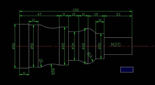
Figure (1)
The tools needed are: sharp knife, 90 degree positive deviation cutter, cutting knife, circular arc knife and thread turning tool.
Also need top, diameter 5 mm center drill, bit chuck, CA6140 ordinary lathe (Dalian Machine Tool Group lathe)
The outer circumferences of the workpieces having diameters of 52, 50, 45, 42, 30, 20 are sequentially processed in order. On the arc surface of R15 and R25 of the workpiece, an outer circle having a diameter of 34 is processed. Then machine the tapered surface and finally machine the circular surface with a radius of 13
Since the maximum size of the workpiece is 52 * 133, all vernier calipers from 0 to 150 are used to measure the size of the workpiece, and thread gages are used to check the thread.
First quarter Selecting blank and turning the outer circle
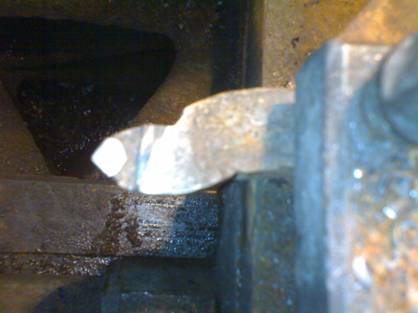
Look for a blank with a diameter of 54 and a length of 200mm to meet the processing conditions. The blank is clamped on the chuck for alignment. The lathe tool is mounted on the square tool table and is pinpointed by the center. To machine the machine switch to power on the machine, adjust the number of revolutions to 350 rpm, the speed of the cutter is II, with a sharp knife (as shown below)
The end face of the blank that is not clamped (ie, the right end face of the blank) is cut. Look at the scale in the X direction and then return along the negative direction of the Y axis. Negative X direction feed tool 2 mm fluctuation X negative direction automatic handle, flat blank end surface with it as the reference plane (as shown).
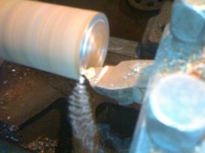
When the knife is about to approach the center of the blank, the automatic knife handle is changed back to manual, the small hand wheel is slowly shaken, the excess blank material is turned to the center of the circle, and the knife is turned back after turning. Clamp the center drill with a collet and clamp the collet to the tailstock. The speed is 350 rpm, the center hole is drilled, the depth is about 8mm, the chuck is taken after drilling, the top is mounted, and the blank is placed against the blank for preparation. Rotate the turret, so that the 90-degree positive-biased knives become the machining knives, and the outer-circle of the blank is cut by the positive-biased knives. The partial knife is shown in the figure.
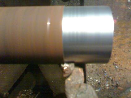
First try to cut, then enter 3mm turning thickness, the number of revolutions 350 is III. Use the automatic to go to the rough car and measure with a caliper to get the outer circle size of 51mm. Then, the spindle rotation speed is adjusted to 450 to the feed speed of II, and the turning thickness is 1 mm. Cutting a length of 133mm, measured as 50mm, FIG.
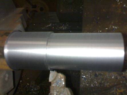
Try cutting it, roughing depth of cut is 3mm, and the speed is the same as above. Finishing of cut to 1mm, and the speed is the same as above, the cutting length of 122mm, measured until the outer dimensions of 45mm, as shown,
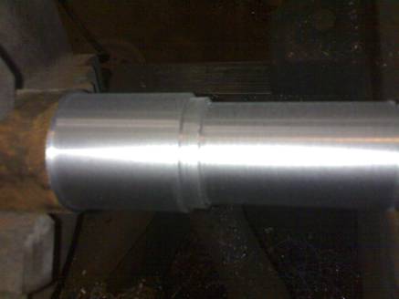
Test cut, into rough finishing, roughing a thickness of 2mm, a thickness of finishing 1mm. The revolutions and speeds of coarse and fine turning are all the same. The cutting length is 52mm, and the cutting size is 42mm. as shown,
Trial cut, the number of revolutions is 400 rpm, and the cutting speed is III. Divided into three rough turning, the amount of knife is 4mm, 4mm, 3mm, the number of revolutions is 480 rpm, and the cutting speed is II. The cutting thickness is 1 mm, the cutting length is 43 mm, and the outer circle size is 30 mm.
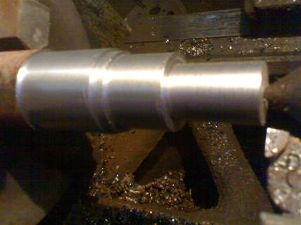
In the trial cut, the number of spindle revolutions and cutting speed of the rough finishing car are the same as in step 4. The rough turning is divided into two times, 4mm, 4mm, the precision turning is 2mm, the cutting length is 33mm, until the size is 20mm, as shown in the figure.
The cutting outer cylindrical surface having a diameter of 42mm and a length of 12mm, cut to a diameter of 35mm
Rotate the small skateboard in a clockwise direction by 13.5 degrees, the spindle rotation number is 400 rpm, and use a circular knife to twist the hand wheel on the small skateboard to turn the conical surface. Starting from the left end of R6, the turning length is 11mm until the size is reached, and then the 45° knives are used to cut the sipe to a diameter of 34mm. The outer diameter of the turning diameter is 52mm, and the length is 11mm. After the above turning, the following figure is obtained.
The number of revolutions is 160 rpm, and the turret is turned to make the sharp knife a machining tool. Use a sharp knife to blunt the sharp points that may be drawn to the hand, and the chamfer is 1*45 degrees.
Turn 160 revolutions per minute, first use the cutting knife to slowly cut a withdrawal groove manually at the far left end of the circular surface with a diameter of 20 mm.
Then use a sharp knife
Set the spindle rotation speed to 320 rpm and turn the screw hole handwheel to the 6 position. The screw rotation mode is B, and the cutting speed is II when turning the thread, and the handle of the clutch is raised to make the spindle rotate forward. Press the threaded snap handle on the slide box, and then make the sharp knife gradually approach the machined surface with the spindle rotating, and try to cut the machined surface. Look at the scale at the small handwheel, retract the knife and press the clutch spindle to reverse the threaded cutter to the right of the workpiece. Turn the small handwheel and feed the knife 0.5mm on the basis of the mark just now, and turn the coarse thread with a diameter of 20mm and a pitch of 2.5mm. Then, when the sharp knife reaches the undercut, the tool is retracted and the clutch is reversed and retracted. Then the tool is turned 0.5mm, and the last feed is 0.25mm, and the thread with a diameter of 20 can be obtained. As shown below,
Third Quarter Cut off
Third Chapter Inspection workpiece
The paper describes the process of processing a cylindrical blank using a conventional lathe. Among them, it mainly involves the processing of the outer circular surface, the processing of the flat end surface, the circular arc surface, the processing of the tapered surface, and the processing of the undercut groove. It also describes the tools needed to machine different shapes and what kind of process should be used to process a blank. As well as the order of processing, more people understand the charm of ordinary lathes.
Key words: cutter; conical surface; circular arc surface; thread; turning speed
Chapter 1 Compiling processing technology
Enter the CAD software, draw the dimensions of the parts to be processed, and mark the part processing dimensions in green, as shown in Figure (1).
Figure (1)
The tools needed are: sharp knife, 90 degree positive deviation cutter, cutting knife, circular arc knife and thread turning tool.
Also need top, diameter 5 mm center drill, bit chuck, CA6140 ordinary lathe (Dalian Machine Tool Group lathe)
The outer circumferences of the workpieces having diameters of 52, 50, 45, 42, 30, 20 are sequentially processed in order. On the arc surface of R15 and R25 of the workpiece, an outer circle having a diameter of 34 is processed. Then machine the tapered surface and finally machine the circular surface with a radius of 13
Since the maximum size of the workpiece is 52 * 133, all vernier calipers from 0 to 150 are used to measure the size of the workpiece, and thread gages are used to check the thread.
Chapter II Workpiece processing
First quarter Selecting blank and turning the outer circle
Look for a blank with a diameter of 54 and a length of 200mm to meet the processing conditions. The blank is clamped on the chuck for alignment. The lathe tool is mounted on the square tool table and is pinpointed by the center. To machine the machine switch to power on the machine, adjust the number of revolutions to 350 rpm, the speed of the cutter is II, with a sharp knife (as shown below)
The end face of the blank that is not clamped (ie, the right end face of the blank) is cut. Look at the scale in the X direction and then return along the negative direction of the Y axis. Negative X direction feed tool 2 mm fluctuation X negative direction automatic handle, flat blank end surface with it as the reference plane (as shown).
First try to cut, then enter 3mm turning thickness, the number of revolutions 350 is III. Use the automatic to go to the rough car and measure with a caliper to get the outer circle size of 51mm. Then, the spindle rotation speed is adjusted to 450 to the feed speed of II, and the turning thickness is 1 mm. Cutting a length of 133mm, measured as 50mm, FIG.
Try cutting it, roughing depth of cut is 3mm, and the speed is the same as above. Finishing of cut to 1mm, and the speed is the same as above, the cutting length of 122mm, measured until the outer dimensions of 45mm, as shown,
Test cut, into rough finishing, roughing a thickness of 2mm, a thickness of finishing 1mm. The revolutions and speeds of coarse and fine turning are all the same. The cutting length is 52mm, and the cutting size is 42mm. as shown,
Trial cut, the number of revolutions is 400 rpm, and the cutting speed is III. Divided into three rough turning, the amount of knife is 4mm, 4mm, 3mm, the number of revolutions is 480 rpm, and the cutting speed is II. The cutting thickness is 1 mm, the cutting length is 43 mm, and the outer circle size is 30 mm.
In the trial cut, the number of spindle revolutions and cutting speed of the rough finishing car are the same as in step 4. The rough turning is divided into two times, 4mm, 4mm, the precision turning is 2mm, the cutting length is 33mm, until the size is 20mm, as shown in the figure.
Use a circular knife (as shown below),
The number of revolutions is 220 rpm, and the arcs of R15 and R25 are turned on an outer circle of 50 mm in diameter. According to the specified size, the previously prepared R15 and R25 molds are compared to the machined circular surface. See which piece does not match the mold and continue to turn until it matches the mold. The finished workpiece is as shown below.
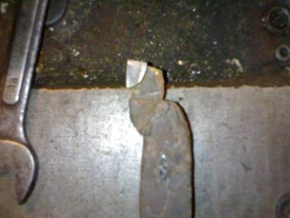
The arc length of the re-turning R6 is 9mm, which is also a little bit turning compared to the mold. Until the mold is intended to match, use a cutting blade with a blade width of 5.5mm (as shown below), the number of revolutions is 160 rpm, manual
The number of revolutions is 220 rpm, and the arcs of R15 and R25 are turned on an outer circle of 50 mm in diameter. According to the specified size, the previously prepared R15 and R25 molds are compared to the machined circular surface. See which piece does not match the mold and continue to turn until it matches the mold. The finished workpiece is as shown below.
The arc length of the re-turning R6 is 9mm, which is also a little bit turning compared to the mold. Until the mold is intended to match, use a cutting blade with a blade width of 5.5mm (as shown below), the number of revolutions is 160 rpm, manual
The cutting outer cylindrical surface having a diameter of 42mm and a length of 12mm, cut to a diameter of 35mm
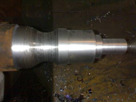
Rotate the small skateboard in a clockwise direction by 13.5 degrees, the spindle rotation number is 400 rpm, and use a circular knife to twist the hand wheel on the small skateboard to turn the conical surface. Starting from the left end of R6, the turning length is 11mm until the size is reached, and then the 45° knives are used to cut the sipe to a diameter of 34mm. The outer diameter of the turning diameter is 52mm, and the length is 11mm. After the above turning, the following figure is obtained.
The number of revolutions is 160 rpm, and the turret is turned to make the sharp knife a machining tool. Use a sharp knife to blunt the sharp points that may be drawn to the hand, and the chamfer is 1*45 degrees.
Section 2 Turning Thread
Turn 160 revolutions per minute, first use the cutting knife to slowly cut a withdrawal groove manually at the far left end of the circular surface with a diameter of 20 mm.
Then use a sharp knife
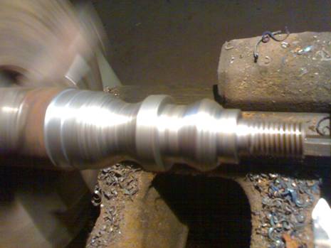
Set the spindle rotation speed to 320 rpm and turn the screw hole handwheel to the 6 position. The screw rotation mode is B, and the cutting speed is II when turning the thread, and the handle of the clutch is raised to make the spindle rotate forward. Press the threaded snap handle on the slide box, and then make the sharp knife gradually approach the machined surface with the spindle rotating, and try to cut the machined surface. Look at the scale at the small handwheel, retract the knife and press the clutch spindle to reverse the threaded cutter to the right of the workpiece. Turn the small handwheel and feed the knife 0.5mm on the basis of the mark just now, and turn the coarse thread with a diameter of 20mm and a pitch of 2.5mm. Then, when the sharp knife reaches the undercut, the tool is retracted and the clutch is reversed and retracted. Then the tool is turned 0.5mm, and the last feed is 0.25mm, and the thread with a diameter of 20 can be obtained. As shown below,
Third Quarter Cut off
Using a cutting blade, the number of revolutions was 160 rpm, and the cutting knife was used to cut from the leftmost end having a diameter of 52 mm.
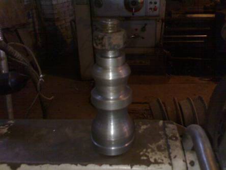
Slowly shake the handwheel, cut off the workpiece, and use 20 nuts to match the thread to get the workpiece as shown.
Remove the workpiece and perform dimensional inspection on the workpiece.
Slowly shake the handwheel, cut off the workpiece, and use 20 nuts to match the thread to get the workpiece as shown.
Remove the workpiece and perform dimensional inspection on the workpiece.
Third Chapter Inspection workpiece
Use vernier caliper 0 ~ 150mm. External measuring claws were used to measure the diameter of the outer circle 52 0.2, 50 0.2, 45 0.2, 34 0.2, 42 0.2, 30 0.2 and length 133. Use the R25 and R13 molds that have been prepared in advance to attach the circular arc surface to see if it fits well. If there is no gap, it proves that the fit is good. If there is a gap, it is unqualified. Use the nut with the inner diameter of M20 to match the thread of M to see if it is consistent. If the nut is screwed to the head, it will be qualified. If it is still shaken, it will be unqualified. (Note: The surface roughness of the workpiece, the thread section needs to be chamfered to ensure the smoothness of the thread.)


