Design of Lathe Processing Process for Precision Shaft Titanium Alloy Parts
Keywords: Titanium Alloy Shaft Parts, Lathe Processing Process, Design Titanium Alloy Parts, Selection of Rough Benchmark, Surface Processing Method of Bearings, Shaft Machining step, Quenching and tempering of titanium
1. Role of Shaft Parts
Output axle of part lathe, its main function, One is to transfer the torque so that the spindle of the lathe can get the power to rotate. Second, it often bears loads in the working process. Third, supporting transmission parts.
2. Process analysis of parts
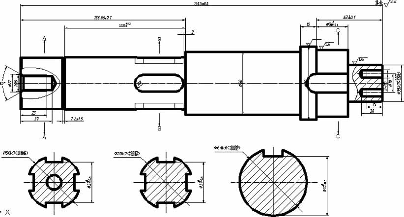
(1) Seen from the part drawings, this part is a typical shaft part, and its structure is relatively simple. The arrangement of the shaft section is ladder-shaped, thick in the middle and thin at both ends. It conforms to the principle of strength and shape, and is easy to install and disassemble.
(2) The main machining faces are φ50, φ60, φ64, φ35, outer cylindrical faces, internal threaded holes of the left end face M16, and two M8 internal threaded holes of the small end faces.
(3) It can be seen in the figure that the dimensional accuracy of parts is high, most of them are IT7 level. The roughness is expressed on the small end cylindrical surface of the shaft, and the outer cylindrical surface of φ64 is Ra1.6um. The end face of the small end is Ra1.6um, and the rest is Ra3.2um, which is relatively high;
(4) Heat treatment requires quenching and tempering treatment, to HRC28-30, to maintain uniformity. Finally, surface oxidation treatment
(5) The material of the part is TC4 Ti-6Al-4V.
(6) The 45° chamfer is machined at the shaft end for ease of assembly.
Four. Selection of blanks and determination of blank size
1. Selection of blanks
(1) The blank material of the part is TC4 Ti-6Al-4V, which is a typical shaft material and is one of the most commonly used titanium alloys. After tempering and surface quenching, better comprehensive properties can be obtained.
(2) Due to the simple status of the workpiece, the profile material TC4 Ti-6Al-4V can be used. The blank is produced by cold drawing. Since the outer circle of Φ70 indicates that the material is not removed, the diameter of the bar is directly selected as Φ70 mm. Check the "Concise Manual of Mechanical Manufacturing Process" to obtain a blank accuracy grade of IT7 and a surface roughness of Ra3.2 to 1.6.
2. Determine the remaining amount of blank
2. Determine the remaining amount of blank
Table 2
V. Design of Process Plans
1. Benchmark selection
(1) Selection of rough reference
The selection of rough datum should ensure the position accuracy between the machined surface and the non-machined surface, reasonably allocate the margin of each machined surface, and provide precise datum for the follow-up process. Therefore, in order to facilitate positioning, clamping and processing, the cylindrical surface of the axis can be selected as the reference, or the cylindrical surface and the apex hole can be used as the reference. When positioning with cylindrical surface, chuck is usually used because of the convenience of datum processing and clamping. In order to ensure that the roughing allowance of the important surface is small and even, the small end axle surface of the part should be selected as the rough reference.
(2) Selection of fine benchmarks
According to the technical requirements and assembly requirements of the output shaft of the reduction gearbox, the right end face of the shaft should be selected as φ50+0.027, +0.002 and end face φ35+0.027, +0.002 as the fine reference. Many surfaces on a part can be machined with the end faces as a reference. Benchmark conversion errors can be avoided and the benchmarking principle is followed. The center axis at both ends is the design basis. The center axis is selected as the reference to ensure the final machining position accuracy of the surface and achieve the coincidence of the design basis and the process reference.
2. Determination of surface processing method for parts
According to the processing requirements of each surface of the part chart, and the material properties, the axis is a stepped shaft, and the specific processing methods of each surface of the shaft are shown in Table 2.
3. Arrangement of Processing Sequence
(1) Mechanical processing
1> Other principles after the first datum plane:
The machining process arrangement always processes the positioning datum first, so it should be arranged to prepare the subsequent process as the benchmark. Firstly, finish the datum plane, turn the center hole and the outer circle of the turning surface.
2> According to the principle of "first rough then fine"
The roughing process is arranged first, followed by the finishing process. First arrange the main surfaces with high precision requirements, and then arrange finishing.
3> According to the principle of priority and priority:
Firstly process the main surface, such as the outer surface of the outer circle, the end surface and so on. Post-processing secondary surfaces, such as milling keyways.
4> first outside and then inside, first big and then small principle: Firstly, the outer circle is processed and then the inner hole is positioned by the outer circle. When the stepped outer circle is processed, the larger diameter is first processed and the smaller diameter is later processed.
5> Minor surface processing arrangement: Processing of secondary surfaces such as keyway is usually arranged after the cylindrical finish turning. For the right end of the axle and the middle end of the axle, the surface with higher processing quality requirements should be arranged at the back.
6> On the right end surface of the shaft is 64mm and intermediate 35mm processing with higher quality requirements, arranged in the back.
7> first face and back hole principle: First machine the end face, then mill the keyway and drill the screw hole.
2) Arrangement of heat treatment process
It is advisable to arrange normalizing before cutting, which can improve the hardness of the shaft, eliminate the internal stress of the blank and improve its cutting performance. After the roughing, the quenching and tempering treatment can improve the overall performance of the shaft. The final heat treatment is arranged after the semi-finishing, which improves the material strength, surface hardness and wear resistance.
After the roughing and heat treatment, the straightening process is arranged. Deburring and intermediate inspection procedures are arranged after semi-finishing. Deburring, cleaning and final inspection procedures are arranged after finishing.
In summary, the sequence of the operation of the shaft is: Benchmark processing_ Main Surface Roughening_ Heat treatment_ Semi-finish Machining of Main Surface_ Finishing (Grinding) of Main Surfaces_ Milling keyway and tapping thread_ Deburring, final heat treatment, etc.
4. The determination of the technological route of the shaft
Based on the analysis of the above processing process, the process route of the parts is determined as shown in Table 4.
5. Machining allowance, process size determination
To determine the process size of the cylindrical surface, the process size of the cylindrical surface for multiple machining is only related to the machining allowance. The total machining allowance (blank allowance) of each cylindrical surface has been determined in the foregoing, and the blank allowance should be divided into machining allowances for each process, and then the process dimensions are calculated from the back to the front. The tolerance of the intermediate process dimensions is determined by the economic accuracy of the machining method. The process allowance, process size and tolerance, and surface roughness of each cylindrical surface of this part are as follows:
Table 5 outer cylindrical surface φ50 Shaft machining allowance calculation
1. Role of Shaft Parts
Output axle of part lathe, its main function, One is to transfer the torque so that the spindle of the lathe can get the power to rotate. Second, it often bears loads in the working process. Third, supporting transmission parts.
2. Process analysis of parts
(1) Seen from the part drawings, this part is a typical shaft part, and its structure is relatively simple. The arrangement of the shaft section is ladder-shaped, thick in the middle and thin at both ends. It conforms to the principle of strength and shape, and is easy to install and disassemble.
(2) The main machining faces are φ50, φ60, φ64, φ35, outer cylindrical faces, internal threaded holes of the left end face M16, and two M8 internal threaded holes of the small end faces.
(3) It can be seen in the figure that the dimensional accuracy of parts is high, most of them are IT7 level. The roughness is expressed on the small end cylindrical surface of the shaft, and the outer cylindrical surface of φ64 is Ra1.6um. The end face of the small end is Ra1.6um, and the rest is Ra3.2um, which is relatively high;
(4) Heat treatment requires quenching and tempering treatment, to HRC28-30, to maintain uniformity. Finally, surface oxidation treatment
(5) The material of the part is TC4 Ti-6Al-4V.
(6) The 45° chamfer is machined at the shaft end for ease of assembly.
Four. Selection of blanks and determination of blank size
1. Selection of blanks
(1) The blank material of the part is TC4 Ti-6Al-4V, which is a typical shaft material and is one of the most commonly used titanium alloys. After tempering and surface quenching, better comprehensive properties can be obtained.
(2) Due to the simple status of the workpiece, the profile material TC4 Ti-6Al-4V can be used. The blank is produced by cold drawing. Since the outer circle of Φ70 indicates that the material is not removed, the diameter of the bar is directly selected as Φ70 mm. Check the "Concise Manual of Mechanical Manufacturing Process" to obtain a blank accuracy grade of IT7 and a surface roughness of Ra3.2 to 1.6.
2. Determine the remaining amount of blank
2. Determine the remaining amount of blank
Table 2
| Simple diagram | Processing Surface Code | Basic dimensions | Machining allowance grade | Machining allowance | Explain |
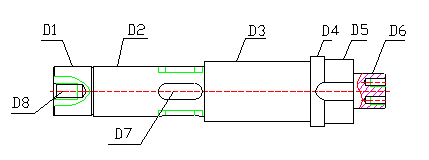 |
D1 | 50 | IT7 | 20 | |
| D2 | 50 | IT7 | 20 | ||
| D3 | 60 | IT7 | 10 | ||
| D4 | 70 | IT7 | |||
| D5 | 64 | IT7 | 6 | ||
| D6 | 35 | IT7 | 35 | ||
| D7 | |||||
| D8 |
V. Design of Process Plans
1. Benchmark selection
(1) Selection of rough reference
The selection of rough datum should ensure the position accuracy between the machined surface and the non-machined surface, reasonably allocate the margin of each machined surface, and provide precise datum for the follow-up process. Therefore, in order to facilitate positioning, clamping and processing, the cylindrical surface of the axis can be selected as the reference, or the cylindrical surface and the apex hole can be used as the reference. When positioning with cylindrical surface, chuck is usually used because of the convenience of datum processing and clamping. In order to ensure that the roughing allowance of the important surface is small and even, the small end axle surface of the part should be selected as the rough reference.
(2) Selection of fine benchmarks
According to the technical requirements and assembly requirements of the output shaft of the reduction gearbox, the right end face of the shaft should be selected as φ50+0.027, +0.002 and end face φ35+0.027, +0.002 as the fine reference. Many surfaces on a part can be machined with the end faces as a reference. Benchmark conversion errors can be avoided and the benchmarking principle is followed. The center axis at both ends is the design basis. The center axis is selected as the reference to ensure the final machining position accuracy of the surface and achieve the coincidence of the design basis and the process reference.
2. Determination of surface processing method for parts
According to the processing requirements of each surface of the part chart, and the material properties, the axis is a stepped shaft, and the specific processing methods of each surface of the shaft are shown in Table 2.
| Machined surface | Dimensional Accuracy Level | Surface roughness Ra(µm) | Processing method |
| Left and right end faces | IT12 | 12.5 | Rough turning |
| Φ50 +0.027, +0.002 outer circular surface | IT7 | 3.2 | Rough turning_semi-finish turning |
| Φ60 outer circular surface | IT7 | 3.2 | Rough turning _ semi-finish turning |
| Φ64 +0.032, +0.002 outer circular surface | IT7 | 1.6 | Rough turning _ semi-finish turning _ Finishing |
| Φ35 +0.027, +0.002 outer circular surface | IT7 | 1.6 | Rough turning _ semi-finish turning _Fine turning |
| Withdrawal groove | IT12 | 12.5 | Fine turning |
| splin | IT7 | 3.2 | Rough Milling _ Semi-Fine Milling |
| Flat key | IT7 | 3.2 | Rough Milling _ Semi-Fine Milling |
| Small end threaded hole | IT12 | 12.5 | Drilling _ tapping |
| Large end threaded hole | IT12 | 12.5 | Drilling _ tapping |
3. Arrangement of Processing Sequence
(1) Mechanical processing
1> Other principles after the first datum plane:
The machining process arrangement always processes the positioning datum first, so it should be arranged to prepare the subsequent process as the benchmark. Firstly, finish the datum plane, turn the center hole and the outer circle of the turning surface.
2> According to the principle of "first rough then fine"
The roughing process is arranged first, followed by the finishing process. First arrange the main surfaces with high precision requirements, and then arrange finishing.
3> According to the principle of priority and priority:
Firstly process the main surface, such as the outer surface of the outer circle, the end surface and so on. Post-processing secondary surfaces, such as milling keyways.
4> first outside and then inside, first big and then small principle: Firstly, the outer circle is processed and then the inner hole is positioned by the outer circle. When the stepped outer circle is processed, the larger diameter is first processed and the smaller diameter is later processed.
5> Minor surface processing arrangement: Processing of secondary surfaces such as keyway is usually arranged after the cylindrical finish turning. For the right end of the axle and the middle end of the axle, the surface with higher processing quality requirements should be arranged at the back.
6> On the right end surface of the shaft is 64mm and intermediate 35mm processing with higher quality requirements, arranged in the back.
7> first face and back hole principle: First machine the end face, then mill the keyway and drill the screw hole.
2) Arrangement of heat treatment process
It is advisable to arrange normalizing before cutting, which can improve the hardness of the shaft, eliminate the internal stress of the blank and improve its cutting performance. After the roughing, the quenching and tempering treatment can improve the overall performance of the shaft. The final heat treatment is arranged after the semi-finishing, which improves the material strength, surface hardness and wear resistance.
After the roughing and heat treatment, the straightening process is arranged. Deburring and intermediate inspection procedures are arranged after semi-finishing. Deburring, cleaning and final inspection procedures are arranged after finishing.
In summary, the sequence of the operation of the shaft is: Benchmark processing_ Main Surface Roughening_ Heat treatment_ Semi-finish Machining of Main Surface_ Finishing (Grinding) of Main Surfaces_ Milling keyway and tapping thread_ Deburring, final heat treatment, etc.
4. The determination of the technological route of the shaft
Based on the analysis of the above processing process, the process route of the parts is determined as shown in Table 4.
| Process ID | Process name | Machine tool equipment | Tool | Measuring tool |
| 01 | Rough turning left and right end faces and 45° chamfering | CA6140 | 45° knife | Vernier caliper |
| 02 | Drill center hole | CA6140 | twist drill | Caliper |
| 03 | Rough turning outer circle | CA6140 | 60° knife | Vernier caliper |
| 04 | Tempered and tempered HRC28~30 | |||
| 05 | Semi-finished turning outer circle φ50, φ60, φ64, φ35 | CA6140 | 60° knife | Vernier calipers and gauges |
| 06 | Fine turning outer circle φ64, φ35 | CA6140 | 60° knife | Vernier caliper |
| 07 | Turning 2.2 x 1.5 slot | CA6140 | Ordinary grooving knife | Vernier caliper |
| 08 | Milling keyway | Milling machine X083 | Milling cutter | Vernier caliper |
| 09 | Drilling M16, 2-M8 threaded holes | Drilling machine Z515 | drill | Vernier caliper |
| 10 | Fitter tapping | Tap | ||
| 11 | Deburring | Hand hammer | ||
| 12 | Final heat treatment (surface oxidation) and cleaning | |||
| 13 | check | Caliper plug |
5. Machining allowance, process size determination
To determine the process size of the cylindrical surface, the process size of the cylindrical surface for multiple machining is only related to the machining allowance. The total machining allowance (blank allowance) of each cylindrical surface has been determined in the foregoing, and the blank allowance should be divided into machining allowances for each process, and then the process dimensions are calculated from the back to the front. The tolerance of the intermediate process dimensions is determined by the economic accuracy of the machining method. The process allowance, process size and tolerance, and surface roughness of each cylindrical surface of this part are as follows:
Table 5 outer cylindrical surface φ50 Shaft machining allowance calculation
| Process name | Inter-process volume/mm | Procedure | Process basic size / mm |
Labeling process Dimensional tolerance / mm |
|
| Economic accuracy / mm | Surface roughness Ra/μm | ||||
| blank | 10 | ±2 | 0 | 60 | Φ60±2 |
| Rough turning | 9 | IT10 | 12.5 | 51.027 | 51.027 0 +0.12 |
| Semi-finishing turning | 1 | IT7 | 3.2 | 50.027 | Φ50.027 0 +027 |


