Design and Research of Deep-hole Machining Negative Pressure Chip Removal Device
Abstract: Deep hole machining technology has always been a key technology in the machinery manufacturing industry. Among them, high-efficient scraps discharge in the machining process is a particularly important part of the deep hole machining process. To solve the problem of slight blockage caused by the unstable shape of the Swarf during deep hole machining, the existing negative pressure Chip remova device was analyzed and analyzed. A pulsed variable-pressure Chip remova device was designed and its theoretical relationship for the formation of variable negative pressure was studied. The feasibility of forming negative pressure was proved theoretically, and simulation analysis was performed by ANSYS FLUENT software. The pulsed variable-voltage Chip remova device enables a pulsed change in the suction force created by the negative pressure Chip remova device. The swarf is subjected to different suction forces. The slightly blocked swarf can be smoothly discharged after changing the direction under changing suction force. So as far as possible to avoid processing failures and improve work efficiency.
Keywords: deep hole machining; efficient scraps discharge; negative pressure Chip remova
Deep-hole machining technology originated from the manufacturing process of gun barrels and was later widely used in civilian fields. The so-called deep hole is the hole whose ratio of hole depth L to hole diameter d is greater than 5. However, due to the large depth of the hole and the diameter, it brings about the problems of low rigidity of the process system, difficult discharge of the swarf, difficulty in cooling and lubrication, etc. Among them, the discharge of the scatters is difficult and bears the brunt. Currently, the common methods for solving the problems of the discharge of the scratchs are as follows: 1 Expand the space of the scraps discharge; 2 Control the shape of the warf; 3 Enhance the power of the scraps discharge.
The negative pressure scrap discharge device solves the problem of difficult discharge of the scraps, and the device adopts a method for increasing the power of the scraps discharge. The suction force generated by the suction effect provides suction discharge power. Practice has proved that the effect of this device is significant, but during the high-speed processing, the swarf accumulates rapidly, and an unqualified swarf is produced, which can easily produce plugging. If it is not discharged in time, it will produce a shwarf accumulation, which will affect the processing quality and production efficiency as well as the service life of the equipment. Therefore, the existing negative pressure Chip remova equipment will not be able to meet the demand for use. The suction force provided by the existing negative pressure scrap discharge device is a fixed value, and can not be effectively discharged when a failed Swarf is encountered, and only the swarf can be continuously increased, eventually causing processing failure. In order to solve the above problem, a negative pressure scraps discharge device is designed by optimizing a negative pressure scrap discharge device. The device can generate a negative pressure in a negative pressure scrap discharge device. The swarf is easy to change direction after being released under a tight suction force, reducing the chance of swart blockage and improving the processing efficiency.
1, negative pressure chip remova device analysis
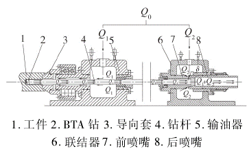
In the traditional negative pressure chip remova device, the cutting fluid is delivered by a metered oil pump while feeding two tributaries, as shown in Fig. 1.

Fig.1 Schematic diagram of the negative pressure Chip remova device
1. Workpiece, 2.BTA drill, 3. Guide sleeve, 4. Oil distributor, 6. Coupling, 7. Front nozzle, 8. Rear nozzle
In this case, the cutting fluid Q1 of the previous branch enters the oil distributor in the scraps discharge channel and flows through the drilling sleeve, the processed hole wall, and the oil-passing gap on the drill rod and the drill body to flow toward the cutting edge of the cutting area. While cooling the blade, push the swarf into the chip remova device after pushing it into the drill pipe. Another Swarf Q2 enters the chip remova device. After passing through the narrow gap between the front and rear nozzles, the flow path becomes smaller and accelerates, and a conical surface jet is formed at the end of the drill rod, so that a negative pressure zone appears at the end of the drill rod. As a result, a suction force to the swarm is generated to accelerate the flow of the medium in the entire scraps discharge channel of the drill rod cavity to achieve the purpose of efficient scraps discharge. The magnitude of the suction force is determined by the flow rate difference between the jet formed by the negative pressure passage and the cutting fluid of the discharge passage. Under the effect of the suction force formed by the negative pressure, the swarf can flow in the drill pipe at high speed, realizing high-speed and high-efficiency scraps discharge.
There are many factors that affect the discharge efficiency of negative pressure scraps. The jet nozzle gap and the jet nozzle jet angle are the main influencing factors. The general jet clearance is 0.2 to 0.5mm, and the injection angle is 15° to 30°. In addition there are some other factors, mainly because of the influence of the negative pressure on the flow in the negative pressure channel. The other factors are assumed to remain unchanged.
2. Pulsed variable negative pressure Chip remova device analysis
2.1 Structural Design
In the negative pressure Chip remova device, it is necessary to realize the negative pressure pulse type change, and it is necessary to change the jet flow of the negative pressure channel in a pulse type. Considering the structure of the negative pressure channel, a simple converter is designed and placed in the negative pressure channel.
The principle of the converter:
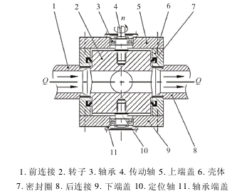
By controlling the rotation of the rotor by the motor, the channel on the rotor is periodically connected to the negative pressure channel. The cross-sectional area of the rotor passage and the negative pressure passage is also periodically changed. The flow through the jet changes periodically, changing the negative pressure. The principle of the converter is shown in Figure 2.

1. Front connection, 2. Rotor, 3. Bearing, 4. Rotating shaft, 5. Upper end cap, 6. Housing, 7. Sealing ring, 8. Lower end cap, 10. Positioning shaft, 11 . Bearing end cap
As shown in Fig. 2, the converter is mainly composed of a shell and a rotor, and both the shell and the rotor are cylindrical structures. Two channels are designed in the middle of the rotor and are perpendicular to each other to provide cutting fluid. When the rotor rotates, the cross-sectional area of the rotor passage that communicates with the negative pressure passage changes. Then the cutting fluid Q is connected from the front to the rotor channel of the converter. The flow rate will inevitably change. The cutting fluid Q enters the rotor channel after passing through the changed cross-sectional area of the rotor channel and the negative pressure channel, and finally enters the negative pressure device after passing through. The rotation of the rotor is provided by a motor connected to the transmission shaft. The size of the motor speed n directly affects the speed of the rotor. The relationship between the speed and the pulse frequency of the cutting fluid is:

2.2 Principle Analysis
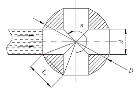
The principle of the converter is that the cutting fluid of the negative pressure channel is periodically passed through the rotation of the rotor, and a pulsed change of the suction force of the negative pressure channel is realized. Now analyze the influence of the parameters of the rotor on the pulse frequency. The cross-sectional view of the rotor is shown in Figure 3.

Through analysis, we can see that the cross-sectional area of the negative pressure channel is determined by the channel diameter d and time t. When the pressure of the cutting fluid entering the converter is constant, the flow rate of the cutting fluid is constant, the cutting fluid flow and the negative pressure channel are horizontal. The cross-sectional area is a proportional relationship and can be calculated quantitatively. However, in actual work, due to factors such as the inertia of the cutting fluid and the rotation of the rotor, the flow rate may be deviated.
4. Conclusion
In this paper, the problem of chip removal during high-speed deep-hole machining is studied, and a pulse-type variable negative pressure chip removal device is designed. The device can create a pulsed variable negative pressure in the chip evacuation passage so that the chip is subjected to a varying suction force. In the case of a slight blockage due to the formation of unsatisfactory chips, since the suction force is tight and loose, the jammed chips are also loosened and changed in direction and then easily discharged. The device makes the negative pressure swarf device more stable and efficient, and improves work efficiency.
Keywords: deep hole machining; efficient scraps discharge; negative pressure Chip remova
Deep-hole machining technology originated from the manufacturing process of gun barrels and was later widely used in civilian fields. The so-called deep hole is the hole whose ratio of hole depth L to hole diameter d is greater than 5. However, due to the large depth of the hole and the diameter, it brings about the problems of low rigidity of the process system, difficult discharge of the swarf, difficulty in cooling and lubrication, etc. Among them, the discharge of the scatters is difficult and bears the brunt. Currently, the common methods for solving the problems of the discharge of the scratchs are as follows: 1 Expand the space of the scraps discharge; 2 Control the shape of the warf; 3 Enhance the power of the scraps discharge.
The negative pressure scrap discharge device solves the problem of difficult discharge of the scraps, and the device adopts a method for increasing the power of the scraps discharge. The suction force generated by the suction effect provides suction discharge power. Practice has proved that the effect of this device is significant, but during the high-speed processing, the swarf accumulates rapidly, and an unqualified swarf is produced, which can easily produce plugging. If it is not discharged in time, it will produce a shwarf accumulation, which will affect the processing quality and production efficiency as well as the service life of the equipment. Therefore, the existing negative pressure Chip remova equipment will not be able to meet the demand for use. The suction force provided by the existing negative pressure scrap discharge device is a fixed value, and can not be effectively discharged when a failed Swarf is encountered, and only the swarf can be continuously increased, eventually causing processing failure. In order to solve the above problem, a negative pressure scraps discharge device is designed by optimizing a negative pressure scrap discharge device. The device can generate a negative pressure in a negative pressure scrap discharge device. The swarf is easy to change direction after being released under a tight suction force, reducing the chance of swart blockage and improving the processing efficiency.
1, negative pressure chip remova device analysis
In the traditional negative pressure chip remova device, the cutting fluid is delivered by a metered oil pump while feeding two tributaries, as shown in Fig. 1.

Fig.1 Schematic diagram of the negative pressure Chip remova device
1. Workpiece, 2.BTA drill, 3. Guide sleeve, 4. Oil distributor, 6. Coupling, 7. Front nozzle, 8. Rear nozzle
In this case, the cutting fluid Q1 of the previous branch enters the oil distributor in the scraps discharge channel and flows through the drilling sleeve, the processed hole wall, and the oil-passing gap on the drill rod and the drill body to flow toward the cutting edge of the cutting area. While cooling the blade, push the swarf into the chip remova device after pushing it into the drill pipe. Another Swarf Q2 enters the chip remova device. After passing through the narrow gap between the front and rear nozzles, the flow path becomes smaller and accelerates, and a conical surface jet is formed at the end of the drill rod, so that a negative pressure zone appears at the end of the drill rod. As a result, a suction force to the swarm is generated to accelerate the flow of the medium in the entire scraps discharge channel of the drill rod cavity to achieve the purpose of efficient scraps discharge. The magnitude of the suction force is determined by the flow rate difference between the jet formed by the negative pressure passage and the cutting fluid of the discharge passage. Under the effect of the suction force formed by the negative pressure, the swarf can flow in the drill pipe at high speed, realizing high-speed and high-efficiency scraps discharge.
There are many factors that affect the discharge efficiency of negative pressure scraps. The jet nozzle gap and the jet nozzle jet angle are the main influencing factors. The general jet clearance is 0.2 to 0.5mm, and the injection angle is 15° to 30°. In addition there are some other factors, mainly because of the influence of the negative pressure on the flow in the negative pressure channel. The other factors are assumed to remain unchanged.
2. Pulsed variable negative pressure Chip remova device analysis
2.1 Structural Design
In the negative pressure Chip remova device, it is necessary to realize the negative pressure pulse type change, and it is necessary to change the jet flow of the negative pressure channel in a pulse type. Considering the structure of the negative pressure channel, a simple converter is designed and placed in the negative pressure channel.
The principle of the converter:
By controlling the rotation of the rotor by the motor, the channel on the rotor is periodically connected to the negative pressure channel. The cross-sectional area of the rotor passage and the negative pressure passage is also periodically changed. The flow through the jet changes periodically, changing the negative pressure. The principle of the converter is shown in Figure 2.

1. Front connection, 2. Rotor, 3. Bearing, 4. Rotating shaft, 5. Upper end cap, 6. Housing, 7. Sealing ring, 8. Lower end cap, 10. Positioning shaft, 11 . Bearing end cap
As shown in Fig. 2, the converter is mainly composed of a shell and a rotor, and both the shell and the rotor are cylindrical structures. Two channels are designed in the middle of the rotor and are perpendicular to each other to provide cutting fluid. When the rotor rotates, the cross-sectional area of the rotor passage that communicates with the negative pressure passage changes. Then the cutting fluid Q is connected from the front to the rotor channel of the converter. The flow rate will inevitably change. The cutting fluid Q enters the rotor channel after passing through the changed cross-sectional area of the rotor channel and the negative pressure channel, and finally enters the negative pressure device after passing through. The rotation of the rotor is provided by a motor connected to the transmission shaft. The size of the motor speed n directly affects the speed of the rotor. The relationship between the speed and the pulse frequency of the cutting fluid is:

2.2 Principle Analysis
The principle of the converter is that the cutting fluid of the negative pressure channel is periodically passed through the rotation of the rotor, and a pulsed change of the suction force of the negative pressure channel is realized. Now analyze the influence of the parameters of the rotor on the pulse frequency. The cross-sectional view of the rotor is shown in Figure 3.

4. Conclusion
In this paper, the problem of chip removal during high-speed deep-hole machining is studied, and a pulse-type variable negative pressure chip removal device is designed. The device can create a pulsed variable negative pressure in the chip evacuation passage so that the chip is subjected to a varying suction force. In the case of a slight blockage due to the formation of unsatisfactory chips, since the suction force is tight and loose, the jammed chips are also loosened and changed in direction and then easily discharged. The device makes the negative pressure swarf device more stable and efficient, and improves work efficiency.


