CNC Machining Process Design and NC Programming of End Cover Parts
Summary: The end cover part is one of the important constructions of the mechanical support connection. The variety of parts is targeted, the production cost is high, and the efficiency is low. It is a typical end cap type part, and its processing is a typical milling process. It is necessary to carefully study the simplification of the processing route, reduce the cost, and improve the efficiency to meet the requirements of low-volume manufacturing. `Considering the multi-tool machining, CNC milling machine choose automatic tool change. Improve the tool rotation speed, slow passes as much as possible one-time processing is completed.
Nc machining process design of the main task is to make processing procedure, also be CNC processing preparation before. Procedure is a regulation parts, walk knife route, size and machine tool of the movement process. Therefore, it is of CNC programming personnel of performance, the manufacture process and operation method it is instructive process documents. Nc machining program is of CNC prescriptive document. CNC machining program should not only including part of the process, but also include of cutting parameter selection, movement way, cutting tool system, cutting norms and clamping workpiece method. Technological procedures set reasonable or not, for programming, machine tools machining efficiency and parts of machining accuracy has important influence. Therefore, we should follow the principle of combining general process of CNC characteristics carefully and clearly stated nc machining process. This design combined with a specific parts parts diagram analysis, processing equipment, tool, tooling choice, cutting speed, feed, optimizing the parameters such as the quantity of back choice, formulate the parts CNC processing technology, According to the choice of machine instruction system wrote parts processing program.
Keywords: nc machining, CNC technology, nc program
2.1.1. Analysis of Part Shape and Features
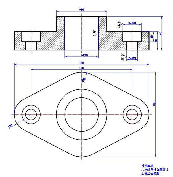
This part is a typical end cover type parts, the composition has an outer surface, a stepped cylinder, the through-bore hole, Mainly for milling, drilling, machining process, available machining center, CNC milling or control drilling parts for processing.
2.1.2. Accuracy Analysis
Dimensional accuracy:
The higher accuracy requirements mainly include Φ40H6. For dimensional accuracy requirements, it is ensured by the precise tool setting in the machining process, the correct selection of the amount of wear of the tool and the correct selection of the appropriate machining process.
Surface roughness:
The main surface roughness has the lowest roughness in the middle hole of 1.6μm, the minimum roughness of the wall on both sides is 3.2μm, and the rest is 12.5μm. For the surface roughness requirements, it is mainly ensured by choosing the right rough and fine processing route, and selecting suitable cutting amount and other measures.
2.2 CNC machining process design
2.2.1. Selecting Positioning Reference
Starting from ensuring the accuracy of workpiece machining, the positioning datum should first select the precise datum and then select the rough datum. The choice of precise benchmark should essentially ensure ensuring the machining accuracy and the installation of workpieces. The principles of selection include the principle of datum overlap, the principle of datum unification, the principle of self reference, the principle of mutual reference and the principle of ease of clamping.
The selection of the rough datum ensures that the machined surfaces have enough machining allowance.Make the position between the processing surface and the non-processing surface conform to the pattern requirements, and pay special attention to obtaining the fine base surface as soon as possible.
The selection principle includes selecting the surface with the most important surface, the unprocessed surface and the smallest machining allowance as the rough datum.
Therefore, end cover parts choose the upper surface as the rough datum and the bottom as the fine datum.
2.2.2. Determine the processing sequence
Arrangement of the cutting sequence: The datum surface is first: the surface to be the fine reference is machined first, and the surface is positioned with the fine base surface.
First plane rear hole: First machining the positioning plane and the end face of the hole, The post-processing hole facilitates the positioning and clamping of the workpiece to be stable and reliable, ensures the positional accuracy of the hole and the plane, and reduces tool wear.
First coarse and fine: Arrange rough machining first (if necessary, semi-finish machining is possible) and then arrange finishing.
First main similar secondary: First arrange the processing of the main surface (such as the assembly base surface, the working surface), and then arrange the processing of the secondary surface (such as the keyway, the threaded hole for fastening); General semi-finishing of the main surface is performed before finishing.
In combination with the above-mentioned part drawing structure process analysis, the principle of process division, and the processing sequence arrangement principle, three processing plans are preliminarily formulated.
The plan is as follows:
(a) The first processing plan:
Milling the top surface - milling the bottom surface - drilling the center hole - Drilling holes on both sides - on both sides of milling holes Φ22 - Drill the middle hole - expand the middle hole - Rough hinge center hole - fine hinge center hole -Deburring
(II) The second processing plan:
Milling the top surface - milling the bottom surface - drilling the center hole - Rough drill center hole - expand the middle hole - Rough hinge center hole - fine hinge middle hole - Drill both sides of the hole - milling both sides Φ22 holes - deburring.
(III) The third processing scheme:
Milling the top surface - milling the bottom surface - Drilling the center hole - drilling holes on both sides - Drill the center hole - drill holes on both sides - expand the middle hole - Rough hinge center hole - fine hinge middle hole - Mill holes on both sides - deburring.
To sum up the above three options, the first one has both the principle of tool concentration and the principle of rough after finishing.
2.3. Determining the type of blank and the dimensions and tolerances of the process
Part simple structure, can be selected as a casting blank, The specific values of the process dimensions and tolerances of the blank are as follows:
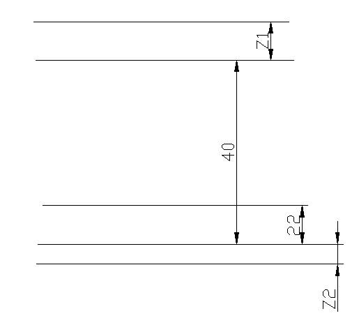
(1) For the top and bottom surfaces, the reference is not coincident and is therefore obtained according to the process size chain method.
(4) For Φ40 hole
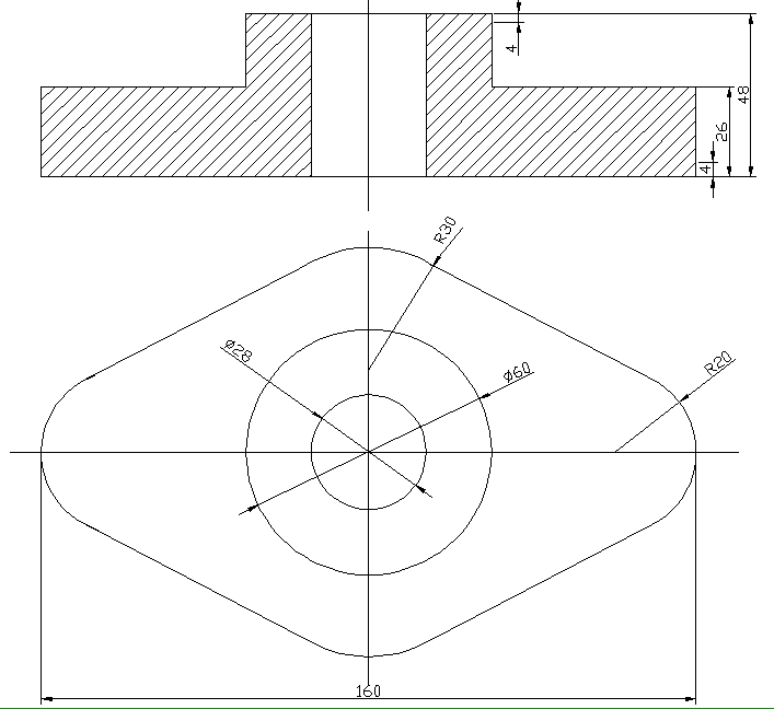
2.4. Determining the total machining allowance and blank size
According to the blank type and processing plan, the blank size is 160mm, 100mm, 40mm, 22mm, R20mm, R30mm, Φ60mm, and its tolerance grade is IT13 grade. The rough figure is as follows:
2.5. Determine the workpiece clamping and positioning scheme
1) As far as possible to achieve the unity of the design process benchmarks and programming calculations
2) Try to reduce the number of clamping operations as much as possible, and process all the processing surfaces after Clamping as much as possible.
3) Avoid using Clamping programs that take long time to manually adjust
4) The point of action of the clamping should fall in a position where the rigidity of the part is better For the structural characteristics of the part, the outer surface of the surface is 60 degrees, and the steps and gaps are clamped by the flat jaws. Milling is contouring using a two-hole positioning method
2.6. Determine the cutting amount for each process
Determination of cutting depth, feed rate, cutting speed and spindle speed.
When selecting the cutting amount, under the premise of guaranteeing the processing quality and the tool durability, The full use of machine performance and tool cutting performance maximizes cutting efficiency and minimizes machining costs. When the tool life is fixed, the cutting speed has the greatest influence on the productivity, the feed rate is the second, and the amount of knife eaten is the smallest.
Therefore, the cutting amount selection principle: First select the maximum depth of cut, then select the maximum amount of feed, and finally select the maximum cutting speed
(1) Selection of cutting depth:
According to the determination of the machining allowance, the cutting process is generally a rough process, semi-finishing and finishing processes, and each process has a different selection method. When roughing (surface roughness ≥12.5), remove all excess of the process as much as possible under permissible conditions. Medium power machine tool, cutting depth up to 8~10mm, But for machining allowances, one pass will result in insufficient machine power or tool strength. Or vibrations caused by uneven allowance, or tool hit by the impact of knives in serious condition arise, we need to use multiple passes; If the knife is divided into two passes, the first cutting depth should be as large as possible, which is generally about 2/3~3/4 of the machining allowance; The second cutting depth should be as small as possible, generally about 1/4 to 1/3 of the machining allowance.
(2) Feed rate selection: According to the hardness of the part material, the tool performs the lookup table selection.
(3) Selection of cutting speed: The cutting depth, feed amount, and tool life are determined and the cutting speed is determined.
(4) Spindle speed Mainly determined by cutting speed:
In summary, the cutting amount for each process is as follows:
1) Milling base surface
Choose machining center vise clamp and carbide face milling cutter.
Ap=4mm f=40mm/min Vc=70m/min nc=180r/min
2) Drill Φ13 hole
Select the drill bit of machining center vise clamp Φ13
Ap=23mm f=30mm/min Vc=20m/min nc=500r/min
3) Milling on the surface
Select one hole and two holes in the machining center. Carbide face milling cutter
Ap=5mm f=40mm/min Vc=70m/min nc=180r/min
4) milling 60 outer circle
Select one hole and two holes in the machining center. Carbide end mill
Ap=0.5mm f=25mm/min Vc=70m/min nc=360r/min
5) Drill Φ40 hole
Select a drill bit with two holes positioned on one side of the machining center
Ap=41mm f=40mm/min Vc=23m/min nc=200/min
5) Milling Φ40 hole
Select one hole and two holes in the machining center. Carbide end mill
Ap=0.5mm f=25mm/min Vc=70m/min nc=360r/min
6) Milling diameter of 22 sinks
Select one hole and two holes in the machining center. Carbide end mill
Ap=0.5mm f=25mm/min Vc=70m/min nc=360r/min
7) Fine Φ40 hole
Select one hole and one hole of the machining center to position Φ40 boring knife
Ap=41mm f=40mm/min Vc=74m/min nc=600r/min
2.8. Tool selection and tool card development
The main considerations for selecting a tool include: Workpiece material, tool material, cutting amount, process system rigidity and other process conditions and machine power.
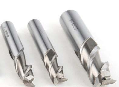
2.8.1. CNC milling cutter
When selecting a tool, the size of the tool must be adapted to the surface size and shape of the workpiece being machined;
At the same time, according to different workpiece materials and machining accuracy requirements, choose different parameters of the milling cutter for processing.
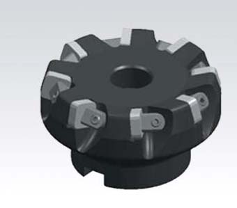
For machining larger planes and larger step surfaces, face milling cutters should be selected;
The vertical milling cutter should be selected for machining peripheral contour, groove and small step surface of plane parts.
Die milling cutter should be selected for machining space surface, mold cavity or punch surface.
For processing of closed keyways, keyway milling cutters should be selected;
The bevel milling cutter should be selected for machining the variable angle surface of the variable angle parts.
Processing three-dimensional profile and variable bevel outline profile, Ball-end cutters and drum cutters are often used;
Machining a variety of straight or arc-shaped grooves, beveled surfaces, special holes should be selected forming cutter.
1) Selection of chip breaker geometry: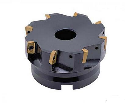
There are three kinds of L, M, H, select the M type
2) Selection of cutter teeth number:
Coarse teeth: Suitable for large margin roughing and milling of soft materials or cutting widths; When the machine power is small, coarse teeth are often used for stable cutting.
Middle teeth: It is a general-purpose system that has a wide range of uses and has a high metal removal rate and cutting stability.
Dense tooth: Mainly used for large feed speed cutting of cast iron, aluminum alloy and non-ferrous metal
Unequal tooth spacing: In order to prevent resonance in the process system, it is used when the cutting is stable.
Select coarse teeth for this part.
3) Selection of the main declination angle:
The lead angle of the milling cutter is formed by the insert and the cutter body, and the main declination angle has a great influence on the radial cutting force and cutting depth. The leading angle is proportional to the radial cutting force. The size of the radial cutting force directly affects the power of the cutting shaft and the vibration resistance of the tool. The smaller the primary angle of the cutter, the smaller the radial cutting force and the better the anti-vibration performance, but the depth of cut is reduced.
The main cutter angle used for this part is 90°
4) Selection of milling cutter diameter:
The face milling cutter diameter is mainly selected according to the workpiece width.
At the same time, consider the power of the machine tool, the position of the tool and the contact form between the tooth and the workpiece. The diameter of the spindle can also be used as the basis for selection. Face milling cutter diameter can be selected according to D = 1.5 d (d: spindle diameter). In general, the diameter of the face milling cutter should be 20%~50% larger than the cut width.
Milling cutter diameter D = 80mm, length L = 220mm
The choice of the diameter of the end mill cutter should mainly consider the requirements of the workpiece processing size, and ensure that the power required by the tool is within the rated power range of the machine tool. Small diameter end mills mainly consider whether the maximum speed of the machine tool can meet the minimum cutting speed requirement of the tool. Select end mill (GB1110-85), end mill diameter D=10mm, length L=72mm
2.8.2. Drill
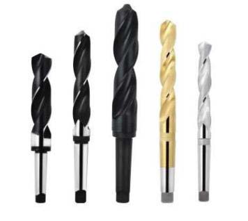
Standard twist drill:
The cutting section has two main cutting edges, two minor cutting edges, one chisel edge, and two spiral grooves.
Drilling a hole in the machining center, Due to the absence of jig drilling guide, the influence of asymmetric cutting forces on the two cutting edges is likely to cause drilling deflection. Therefore, it is required that the two cutting edges of the drill must have high sharpening accuracy.
The selected carbide drill shank twist drill (GB1436-85) diameter D = 13mm, length L = 151mm
Hard alloy taper shank twist drill (GB1438-85) diameter D = 38mm, length L = 349mm Carbide taper shank reamer (GB1141-84) diameter D = 39.6mm, length L = 349mm.
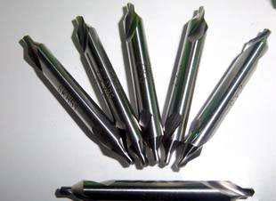 2.8.3. Central drill
It is mainly used for the positioning of the hole. Because the diameter of the cutting part is small, a higher rotation speed should be selected when drilling the center hole.
Type A center drill without guard cone: When processing center hole with diameter d=1-10mm, A type is usually used;
B-type center drill with guard cone: when processing diameter d = 1-10mm center hole, the work procedure is longer and the workpiece with higher precision is required. In order to avoid the damage of the 60 degree centering cone, type B is generally adopted;
Type C: threaded center drill;
R-type arc center drill: When machining a shaft with a diameter of d = 1-10mm and the positioning accuracy is relatively high (such as a round broach), the R type is used. This part is selected from type A center drill without guard cone diameter D = 2mm, length L = 220mm.
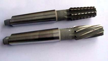 2.8.4. Reamer
Used for machining centers.
Reaming machining accuracy can reach IT9~IT8 level, and the surface roughness can reach 1.6~0.8μm.
The taper shank reamer diameter is 10~32mm, the straight shank reamer diameter is 6~20mm;
Small hole straight shank reamer diameter 1~6mm; sleeve reamer diameter 1~6mm
Here the processing is selected from carbide Morse taper shank machine reamers (GB4252-2004), diameter D = 40mm. Length L = 329mm
2.9. CNC machining program description
The program name is O0002
N100-N128 is milled on the top surface and the starting point is X-146.089 Y-49.998 Milling depth Z-3mm
N130-N142 drill Φ13 hole left (right) hole starting point X-60.Y0 (X60.Y0) drilling depth Z-49
N144-N202 Milling Φ22 Groove left (right) Starting point X-60.026Y-3.5 (X60.026Y3.5) Milling deep Z-29
N208- N218 Drill Center Hole Φ38 From Tool Point X0.Y0 Drill Deep Z-55
Expand Φ38 to Φ39.8 (This program is not listed)
N2028- N2038 Hinge Center Hole Φ40 from Tool Point X0.Y0 Hinge depth Z-45
Nc machining process design of the main task is to make processing procedure, also be CNC processing preparation before. Procedure is a regulation parts, walk knife route, size and machine tool of the movement process. Therefore, it is of CNC programming personnel of performance, the manufacture process and operation method it is instructive process documents. Nc machining program is of CNC prescriptive document. CNC machining program should not only including part of the process, but also include of cutting parameter selection, movement way, cutting tool system, cutting norms and clamping workpiece method. Technological procedures set reasonable or not, for programming, machine tools machining efficiency and parts of machining accuracy has important influence. Therefore, we should follow the principle of combining general process of CNC characteristics carefully and clearly stated nc machining process. This design combined with a specific parts parts diagram analysis, processing equipment, tool, tooling choice, cutting speed, feed, optimizing the parameters such as the quantity of back choice, formulate the parts CNC processing technology, According to the choice of machine instruction system wrote parts processing program.
Keywords: nc machining, CNC technology, nc program
Chapter 1 NC Machining Process of End Cap Parts
2.1 Process Analysis of CNC Machining Parts2.1.1. Analysis of Part Shape and Features
This part is a typical end cover type parts, the composition has an outer surface, a stepped cylinder, the through-bore hole, Mainly for milling, drilling, machining process, available machining center, CNC milling or control drilling parts for processing.
2.1.2. Accuracy Analysis
Dimensional accuracy:
The higher accuracy requirements mainly include Φ40H6. For dimensional accuracy requirements, it is ensured by the precise tool setting in the machining process, the correct selection of the amount of wear of the tool and the correct selection of the appropriate machining process.
Surface roughness:
The main surface roughness has the lowest roughness in the middle hole of 1.6μm, the minimum roughness of the wall on both sides is 3.2μm, and the rest is 12.5μm. For the surface roughness requirements, it is mainly ensured by choosing the right rough and fine processing route, and selecting suitable cutting amount and other measures.
2.2 CNC machining process design
2.2.1. Selecting Positioning Reference
Starting from ensuring the accuracy of workpiece machining, the positioning datum should first select the precise datum and then select the rough datum. The choice of precise benchmark should essentially ensure ensuring the machining accuracy and the installation of workpieces. The principles of selection include the principle of datum overlap, the principle of datum unification, the principle of self reference, the principle of mutual reference and the principle of ease of clamping.
The selection of the rough datum ensures that the machined surfaces have enough machining allowance.Make the position between the processing surface and the non-processing surface conform to the pattern requirements, and pay special attention to obtaining the fine base surface as soon as possible.
The selection principle includes selecting the surface with the most important surface, the unprocessed surface and the smallest machining allowance as the rough datum.
Therefore, end cover parts choose the upper surface as the rough datum and the bottom as the fine datum.
2.2.2. Determine the processing sequence
Arrangement of the cutting sequence: The datum surface is first: the surface to be the fine reference is machined first, and the surface is positioned with the fine base surface.
First plane rear hole: First machining the positioning plane and the end face of the hole, The post-processing hole facilitates the positioning and clamping of the workpiece to be stable and reliable, ensures the positional accuracy of the hole and the plane, and reduces tool wear.
First coarse and fine: Arrange rough machining first (if necessary, semi-finish machining is possible) and then arrange finishing.
First main similar secondary: First arrange the processing of the main surface (such as the assembly base surface, the working surface), and then arrange the processing of the secondary surface (such as the keyway, the threaded hole for fastening); General semi-finishing of the main surface is performed before finishing.
In combination with the above-mentioned part drawing structure process analysis, the principle of process division, and the processing sequence arrangement principle, three processing plans are preliminarily formulated.
The plan is as follows:
(a) The first processing plan:
Milling the top surface - milling the bottom surface - drilling the center hole - Drilling holes on both sides - on both sides of milling holes Φ22 - Drill the middle hole - expand the middle hole - Rough hinge center hole - fine hinge center hole -Deburring
(II) The second processing plan:
Milling the top surface - milling the bottom surface - drilling the center hole - Rough drill center hole - expand the middle hole - Rough hinge center hole - fine hinge middle hole - Drill both sides of the hole - milling both sides Φ22 holes - deburring.
(III) The third processing scheme:
Milling the top surface - milling the bottom surface - Drilling the center hole - drilling holes on both sides - Drill the center hole - drill holes on both sides - expand the middle hole - Rough hinge center hole - fine hinge middle hole - Mill holes on both sides - deburring.
To sum up the above three options, the first one has both the principle of tool concentration and the principle of rough after finishing.
2.3. Determining the type of blank and the dimensions and tolerances of the process
Part simple structure, can be selected as a casting blank, The specific values of the process dimensions and tolerances of the blank are as follows:
(1) For the top and bottom surfaces, the reference is not coincident and is therefore obtained according to the process size chain method.
After checking the table Z1=Z2=4mm, z1 and z2 are machining allowances. The economic accuracy of the process is IT12.
(2) For Φ13 holes|
Process name |
Process margin | Process economic accuracy | Process basic size | Process dimensions and tolerances |
| Drilling | 13 | 0.22 | 13 |
|
| blank |
(4) For Φ40 hole
| Process name | Process margin | Process economic accuracy | Process basic size | Process dimensions and tolerances |
| Precision hinge | 0.07 | 0.025 | 40 | |
| Crude hinge | 0.15 | 0.074 | 40-0.07=39.93 | |
| Expand | 1.75 | 0.16 | 39.9-0.15=39.75 | |
| Drilling | 10 | 0.25 | 39.75-1.75=38 | |
| blank | 28 | 0.21 |
2.4. Determining the total machining allowance and blank size
According to the blank type and processing plan, the blank size is 160mm, 100mm, 40mm, 22mm, R20mm, R30mm, Φ60mm, and its tolerance grade is IT13 grade. The rough figure is as follows:
2.5. Determine the workpiece clamping and positioning scheme
1) As far as possible to achieve the unity of the design process benchmarks and programming calculations
2) Try to reduce the number of clamping operations as much as possible, and process all the processing surfaces after Clamping as much as possible.
3) Avoid using Clamping programs that take long time to manually adjust
4) The point of action of the clamping should fall in a position where the rigidity of the part is better For the structural characteristics of the part, the outer surface of the surface is 60 degrees, and the steps and gaps are clamped by the flat jaws. Milling is contouring using a two-hole positioning method
2.6. Determine the cutting amount for each process
Determination of cutting depth, feed rate, cutting speed and spindle speed.
When selecting the cutting amount, under the premise of guaranteeing the processing quality and the tool durability, The full use of machine performance and tool cutting performance maximizes cutting efficiency and minimizes machining costs. When the tool life is fixed, the cutting speed has the greatest influence on the productivity, the feed rate is the second, and the amount of knife eaten is the smallest.
Therefore, the cutting amount selection principle: First select the maximum depth of cut, then select the maximum amount of feed, and finally select the maximum cutting speed
(1) Selection of cutting depth:
According to the determination of the machining allowance, the cutting process is generally a rough process, semi-finishing and finishing processes, and each process has a different selection method. When roughing (surface roughness ≥12.5), remove all excess of the process as much as possible under permissible conditions. Medium power machine tool, cutting depth up to 8~10mm, But for machining allowances, one pass will result in insufficient machine power or tool strength. Or vibrations caused by uneven allowance, or tool hit by the impact of knives in serious condition arise, we need to use multiple passes; If the knife is divided into two passes, the first cutting depth should be as large as possible, which is generally about 2/3~3/4 of the machining allowance; The second cutting depth should be as small as possible, generally about 1/4 to 1/3 of the machining allowance.
(2) Feed rate selection: According to the hardness of the part material, the tool performs the lookup table selection.
(3) Selection of cutting speed: The cutting depth, feed amount, and tool life are determined and the cutting speed is determined.
(4) Spindle speed Mainly determined by cutting speed:
In summary, the cutting amount for each process is as follows:
1) Milling base surface
Choose machining center vise clamp and carbide face milling cutter.
Ap=4mm f=40mm/min Vc=70m/min nc=180r/min
2) Drill Φ13 hole
Select the drill bit of machining center vise clamp Φ13
Ap=23mm f=30mm/min Vc=20m/min nc=500r/min
3) Milling on the surface
Select one hole and two holes in the machining center. Carbide face milling cutter
Ap=5mm f=40mm/min Vc=70m/min nc=180r/min
4) milling 60 outer circle
Select one hole and two holes in the machining center. Carbide end mill
Ap=0.5mm f=25mm/min Vc=70m/min nc=360r/min
5) Drill Φ40 hole
Select a drill bit with two holes positioned on one side of the machining center
Ap=41mm f=40mm/min Vc=23m/min nc=200/min
5) Milling Φ40 hole
Select one hole and two holes in the machining center. Carbide end mill
Ap=0.5mm f=25mm/min Vc=70m/min nc=360r/min
6) Milling diameter of 22 sinks
Select one hole and two holes in the machining center. Carbide end mill
Ap=0.5mm f=25mm/min Vc=70m/min nc=360r/min
7) Fine Φ40 hole
Select one hole and one hole of the machining center to position Φ40 boring knife
Ap=41mm f=40mm/min Vc=74m/min nc=600r/min
2.8. Tool selection and tool card development
The main considerations for selecting a tool include: Workpiece material, tool material, cutting amount, process system rigidity and other process conditions and machine power.
2.8.1. CNC milling cutter
When selecting a tool, the size of the tool must be adapted to the surface size and shape of the workpiece being machined;
At the same time, according to different workpiece materials and machining accuracy requirements, choose different parameters of the milling cutter for processing.
For machining larger planes and larger step surfaces, face milling cutters should be selected;
The vertical milling cutter should be selected for machining peripheral contour, groove and small step surface of plane parts.
Die milling cutter should be selected for machining space surface, mold cavity or punch surface.
For processing of closed keyways, keyway milling cutters should be selected;
The bevel milling cutter should be selected for machining the variable angle surface of the variable angle parts.
Processing three-dimensional profile and variable bevel outline profile, Ball-end cutters and drum cutters are often used;
Machining a variety of straight or arc-shaped grooves, beveled surfaces, special holes should be selected forming cutter.
1) Selection of chip breaker geometry:
There are three kinds of L, M, H, select the M type
2) Selection of cutter teeth number:
Coarse teeth: Suitable for large margin roughing and milling of soft materials or cutting widths; When the machine power is small, coarse teeth are often used for stable cutting.
Middle teeth: It is a general-purpose system that has a wide range of uses and has a high metal removal rate and cutting stability.
Dense tooth: Mainly used for large feed speed cutting of cast iron, aluminum alloy and non-ferrous metal
Unequal tooth spacing: In order to prevent resonance in the process system, it is used when the cutting is stable.
Select coarse teeth for this part.
3) Selection of the main declination angle:
The lead angle of the milling cutter is formed by the insert and the cutter body, and the main declination angle has a great influence on the radial cutting force and cutting depth. The leading angle is proportional to the radial cutting force. The size of the radial cutting force directly affects the power of the cutting shaft and the vibration resistance of the tool. The smaller the primary angle of the cutter, the smaller the radial cutting force and the better the anti-vibration performance, but the depth of cut is reduced.
The main cutter angle used for this part is 90°
4) Selection of milling cutter diameter:
The face milling cutter diameter is mainly selected according to the workpiece width.
At the same time, consider the power of the machine tool, the position of the tool and the contact form between the tooth and the workpiece. The diameter of the spindle can also be used as the basis for selection. Face milling cutter diameter can be selected according to D = 1.5 d (d: spindle diameter). In general, the diameter of the face milling cutter should be 20%~50% larger than the cut width.
Milling cutter diameter D = 80mm, length L = 220mm
The choice of the diameter of the end mill cutter should mainly consider the requirements of the workpiece processing size, and ensure that the power required by the tool is within the rated power range of the machine tool. Small diameter end mills mainly consider whether the maximum speed of the machine tool can meet the minimum cutting speed requirement of the tool. Select end mill (GB1110-85), end mill diameter D=10mm, length L=72mm
2.8.2. Drill
Standard twist drill:
The cutting section has two main cutting edges, two minor cutting edges, one chisel edge, and two spiral grooves.
Drilling a hole in the machining center, Due to the absence of jig drilling guide, the influence of asymmetric cutting forces on the two cutting edges is likely to cause drilling deflection. Therefore, it is required that the two cutting edges of the drill must have high sharpening accuracy.
The selected carbide drill shank twist drill (GB1436-85) diameter D = 13mm, length L = 151mm
Hard alloy taper shank twist drill (GB1438-85) diameter D = 38mm, length L = 349mm Carbide taper shank reamer (GB1141-84) diameter D = 39.6mm, length L = 349mm.
It is mainly used for the positioning of the hole. Because the diameter of the cutting part is small, a higher rotation speed should be selected when drilling the center hole.
Type A center drill without guard cone: When processing center hole with diameter d=1-10mm, A type is usually used;
B-type center drill with guard cone: when processing diameter d = 1-10mm center hole, the work procedure is longer and the workpiece with higher precision is required. In order to avoid the damage of the 60 degree centering cone, type B is generally adopted;
Type C: threaded center drill;
R-type arc center drill: When machining a shaft with a diameter of d = 1-10mm and the positioning accuracy is relatively high (such as a round broach), the R type is used. This part is selected from type A center drill without guard cone diameter D = 2mm, length L = 220mm.
Used for machining centers.
Reaming machining accuracy can reach IT9~IT8 level, and the surface roughness can reach 1.6~0.8μm.
The taper shank reamer diameter is 10~32mm, the straight shank reamer diameter is 6~20mm;
Small hole straight shank reamer diameter 1~6mm; sleeve reamer diameter 1~6mm
Here the processing is selected from carbide Morse taper shank machine reamers (GB4252-2004), diameter D = 40mm. Length L = 329mm
2.9. CNC machining program description
The program name is O0002
N100-N128 is milled on the top surface and the starting point is X-146.089 Y-49.998 Milling depth Z-3mm
N130-N142 drill Φ13 hole left (right) hole starting point X-60.Y0 (X60.Y0) drilling depth Z-49
N144-N202 Milling Φ22 Groove left (right) Starting point X-60.026Y-3.5 (X60.026Y3.5) Milling deep Z-29
N208- N218 Drill Center Hole Φ38 From Tool Point X0.Y0 Drill Deep Z-55
Expand Φ38 to Φ39.8 (This program is not listed)
N2028- N2038 Hinge Center Hole Φ40 from Tool Point X0.Y0 Hinge depth Z-45


