45# Steel Base Parts CNC Process Design
In this paper, through the analysis of a simple base part structure designed by ourselves, and programming, drilling, milling and other numerical control machining, it can better meet the actual precision requirements and improve the processing quality and design efficiency.
Analyze parts from the structure and formulate the process specifications required for processing, from the determination of the blank to the design process route.
Select the appropriate machine tool, tool, corresponding fixture, preparation of the machining program and inspection of the part according to the requirements. The programming of the program is generated by the combination of MasterCAM automatic programming and manual programming.
Keywords: CNC machining, CNC programming, Pro/E, AutoCAD
With the rapid development of science and technology, social demands on the mechanical product structure, performance, accuracy, efficiency and variety of increasingly high proportion of single-piece and small batch production is growing (now accounts for more than 70%) , Traditional general-purpose, special-purpose machine tools and process equipment are not well suited to high-quality, high-efficiency, and diverse processing requirements. Therefore, the numerical control technology based on microelectronics technology and computer technology organically combines mechanical technology, modern control technology, sensing detection technology, information processing technology, network communication technology and group technology. The production methods and machine manufacturing technologies of the machine manufacturing industry have undergone profound and revolutionary changes.
processing analysis of the base parts
2.1 Check the table to select different parts, the table is as follows:
Table 2-1 Grades, compositions, properties and uses of steel
Table 2-3 grades, mechanical properties and uses (from GB9439-88)
2.2 Fixture, tool selection and cutting amount setting
2.2.1 Selection of fixtures and setting of workpiece clamping method
1. Fixture selection
There are two major requirements for CNC machining on fixtures: first, the fixture should have sufficient accuracy and rigidity; second, the fixture should have a reliable positioning reference.
2. Type of fixture
There are two main types of fixtures on CNC lathes: one for discs or short shafts.
The workpiece blank is clamped in a chuck with adjustable claws (three claws, four claws), and is rotated by the chuck drive; The other type is used for shaft parts, and the blank is placed between the top of the spindle and the tip of the tailstock. Toggle the workpiece chuck is rotated by the spindle drive. CNC milling jig, typically mounted on a table, which may be varied according to the form of the workpiece features.
Such as: general bench vise, CNC indexing turntable, etc.
2.2.2 Tool selection and setting of tool point and tool change point
1. Tool selection
Compared with the ordinary machine tool processing method, CNC machining puts higher requirements on the tool, not only requires good rigidity, high precision, but also requires dimensional stability, high durability, good chip breaking and chip discharging performance; At the same time, it is easy to install and adjust, so as to meet the high efficiency requirements of CNC machine tools. The tools selected for CNC machine tools often use tool materials that are suitable for high-speed cutting (such as high-speed steel, ultra-fine-grained carbide) and use indexable inserts.
(1) Cutting tools and their choices The commonly used turning tools for CNC turning are generally divided into three types: sharp turning tool , circular-shaped turning tools and forming turning tools.
1) Pointed turning tool The pointed turning tool is a turning tool characterized by a linear cutting edge.
The tip of this type of turning tool consists of a straight primary and secondary cutting edge.
For example, 90° inner and outer round turning tools, left and right end turning tools, grooving (cutting) turning tools and various outer and inner hole turning tools with small chamfering edges. The selection method of the geometric parameters of the pointed tool (mainly geometric angle) is basically the same as that of ordinary turning. However, it should be considered in combination with the characteristics of CNC machining (such as machining route, machining interference, etc.), and should take into account the strength of the tool tip itself.
2) The circular turning tool is a turning tool characterized by a circular arc-shaped cutting edge with a small roundness or line contour error. Each point of the turning edge of the turning tool is the tip of the circular arc turning tool. Therefore, the tool point is not on the arc but on the center of the arc.
The circular turning tool can be used for turning the inner and outer surfaces, and is particularly suitable for turning various smooth joints (concave) forming surfaces. Two points should be considered when selecting the arc radius of the turning tool: First, the arc radius of the cutting edge of the turning tool should be less than or equal to the minimum radius of curvature on the concave contour of the part to avoid machining interference; Second, the radius should not be chosen too small, otherwise it will not only be difficult to manufacture, but also cause the tool to be damaged due to the weakness of the tip or the poor heat dissipation of the blade.
3) Forming turning tools are also called model turning tools. The contour shape of the machined parts is completely determined by the shape and size of the tool blade.
In CNC turning, common forming turning tools include small radius arc turning tools, non-rectangular grooving knives and thread knives. NC machining, molding tools should be used sparingly or not.
4) When milling the bottom of the inner groove with a flat-bottom end mill, the lap radius of the bottom edge of the groove is required to be overlapped, and the radius of the bottom edge of the tool is Re=R-r. That is, the diameter is d=2 Re=2(R-r), and the tool radius is set to Re=0.95 (R-r) during programming. For the machining of some three-dimensional and variable-angle contours, spherical milling cutters, ring milling cutters, drum milling cutters, conical milling cutters and disc milling cutters are commonly used.
(3) Standardized tools: At present, most of the CNC machine tools use serialized and standardized tools. There are national standard and serialized models for the shank and cutter head of the indexing machine with external turning tools and end turning tools; For machining centers and machine tools with automatic tool changers, the tool holders have been serialized and standardized. For example, the standard code of the taper tool system is TSG-JT, and the standard code of the straight tool system is DSG-JZ.
2. Setting of the cutter point and tool change point
After the machine tool is determined, the workpiece coordinate system is determined by determining the workpiece origin. The motion axis codes in the machining program control the relative displacement of the tool. For example, the first block of a program starts with N0010 G90 G00 X100 Z20, which means that the tool moves quickly to the workpiece coordinate X=100mm Z=20mm.
Where does the tool move from the position to the above position?
Therefore, at the beginning of the program execution, it is necessary to determine the position at which the tool starts moving in the workpiece coordinate system. This position is the starting point of the tool movement relative to the workpiece during program execution, so it is called the program starting point or the starting point. This starting point is generally determined by the tool setting, so this point is also called the cutter point.
When programming, it is necessary to correctly select the position of the tool point. The principle of setting the knife point is:
1) Facilitate numerical processing and simplify programming.
2) Easy to align and easy to check during processing.
3) The processing error caused is small.
The tool point can be set on the machined part or on the fixture or on the machine. In order to improve the machining accuracy of the part, the tool point should be set as much as possible on the design basis or process reference of the part. Example: To position a part by a circle or a hole, the intersection of the center and the end of the outer circle or hole can be taken as the tool point.
When the machine is actually operated, the tool position of the tool can be placed on the tool point by manual tool setting operation, that is, the “cutter-location point” and the “ cutter point” coincide. The so-called "tool position point" refers to the positioning reference point of the tool, and the tool position of the turning tool is the tool tip or the center of the tool edge arc; The flat end mill is the intersection of the tool axis and the bottom surface of the tool; The ball end milling cutter is the center of the ball head, and the drill bit is the drill tip. With manual tool setting, the tool setting accuracy is low and the efficiency is low. In some factories, optical pairing mirrors, tool setting instruments, and automatic tool setting devices are used to reduce tooling time and improve tool setting accuracy.
When a tool change is required during machining, the tool change point should be specified. The so-called "tool change point" refers to the position when the tool holder is rotated and the tool change point is set. The tool change point should be set outside the workpiece or the clamp, and the workpiece and other components are not affected when the tool is changed.
2.2.3 Determination of cutting amount
During NC programming, the programmer must determine the amount of cut for each process and write it in the program as an instruction. Cutting quantities include spindle speed, depth of cut, and feed rate. For different processing methods, different cutting amounts are required. The selection principle for cutting amount is: Ensure the machining accuracy and surface roughness of the parts, give full play to the cutting performance of the tool, and ensure reasonable tool durability; And give full play to the performance of the machine to maximize productivity and reduce costs.
1. Spindle speed determination
The spindle speed should be selected based on the allowable cutting speed and the workpiece (or tool) diameter. Its calculation formula is:
n=1000v/πD
In the middle
v----cutting speed in m/min, determined by the durability of the tool;
N-- - spindle speed in r/min;
D----Workpiece diameter or tool diameter in mm.
The calculated spindle speed n is finally selected according to the machine tool specification.
2. Determination of feed rate
The feed rate is an important parameter in the cutting amount of CNC machine tools. It is mainly selected according to the machining accuracy and surface roughness requirements of the parts and the material properties of the tools and workpieces. The maximum feed rate is limited by the machine stiffness and the performance of the feed system.
The principle of determining the feed rate:
1) When the quality requirements of the workpiece can be guaranteed, in order to improve production efficiency, a higher feed rate can be selected. Generally, it is selected in the range of 100 to 200 mm/min.
2) When cutting or machining deep holes or machining with high speed steel tools, it is advisable to select a lower feed rate, generally in the range of 20 to 50 mm/min.
3) When the machining accuracy and surface roughness are high, the feed rate should be selected to be smaller, generally in the range of 20 to 50 mm/min.
4) When the tool is in the free travel, especially when the distance is “return to zero”, the maximum feed speed set by the CNC system of the machine can be set.
3. Depth of cut
The depth of cut is determined by the stiffness of the machine tool, workpiece and tool. Under the condition of stiffness, the depth of cut should be equal to the machining allowance of the workpiece. This can reduce the number of passes and increase the production efficiency. In order to ensure the quality of the machined surface, a small amount of finishing allowance can be left, generally 0.2 to 0.5 mm. In summary, the specific value of the cutting amount should be determined by analogy based on machine performance, relevant manuals and practical experience. At the same time, the spindle speed, depth of cut and feed rate can be adapted to each other to form the optimum cutting amount.
2.3 Base CNC machining process specification:
2.3.1 Analysis of parts drawing:
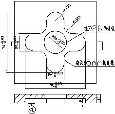
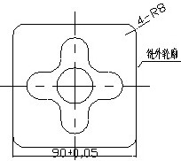
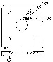
The parts to be processed are shown in the figure, the material is HT200, the blank is 300×250×50 square material, and the single piece is produced by vertical milling machine. The outer contour of the blank was machined into a base of 285 x 240 x 45 and a rounded corner R = 8 mm. A through hole of diameter Ф=26 mm is milled in the center of the top surface of the base, and a cross-shaped groove is cut beside it, the depth is 5 mm, and the detailed dimensions are as shown. A groove having a depth of 1.5 mm is milled on the bottom surface of the blank to leave four protrusions on the bottom surface.
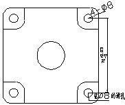
A through hole with a radius R=8 mm is drilled on the base.
2.3.2 Review of the parts drawing: the examination is qualified.
2.3.3 production program: single piece, small batch.
2.3.4 Determining the blank:
The blank material is LY12, which is cold-rolled and has a blank size of 95×95×10.
2.3.5 Process Route:
The bottom surface of the blank is used as a machining reference, and the holes, grooves, and contours are machined by milling, and the small holes are processed by drilling. In order to ensure the quality of the part processing, the processing stage is divided into the roughing stage, the finishing stage, and the process is organized according to the principle of process dispersion.
2.3.6 Determine the machining allowance for each process and calculate the process dimensions and tolerances:
1. The machining allowance for the hole and the upper and lower grooves is 0.2.
2. The design requirements of the large through hole are: 260+0.052, Ra=1.6, and the edge of the hole is perpendicular to the bottom surface with a tolerance of 0.02.
The groove design next to the through hole requires:
1) The depth is 5+0.048, and the bottom edge requires a parallelism tolerance of 0.02 based on the bottom surface.
2) The width of the four corners of the groove is designed to be: 20+0.033
The four sides of the square base are designed to be 90 ± 0.05.
Design requirements for the bottom groove: 1.5mm depth, no tolerance requirements.
Four small through hole design requirements for the base:
1) The distance between adjacent holes is designed to be 70+0.03.
2) Hole design requirements: A through hole with a diameter Ф=8 is required.
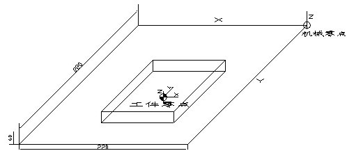
2.4 CNC programming coordinate system:
The coordinate system is established with the center of the workpiece as the origin. The coordinate axis parallel to the spindle is the Z coordinate axis, and the direction of the tool away from the workpiece is the positive direction. It is perpendicular to the Z axis and parallel to the workpiece clamping plane in the X direction. When viewed in the direction of the main axial column of the tool, the tool direction is again in the +X direction. The Y axis is perpendicular to the X and Z coordinates, and the +Y direction is determined by the right hand flute method.
2.5 parts CNC machining program:
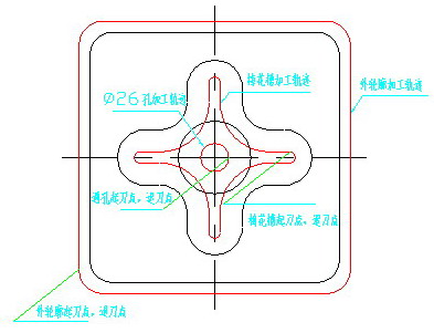
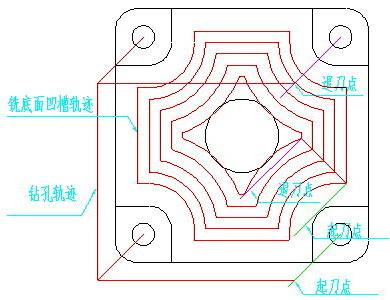
2.6 processing track:
Machining program simulation check:
It can be simulated in the numerical control laboratory and can simulate its processing trajectory.
Summary
Through this design, the entire process of CNC machining has a comprehensive understanding. Through reading the map and reviewing the map, I have a deeper understanding of the mechanical drawings, and enhanced my ability to map, and at the same time, avoid many mistakes when drawing my own drawings;
By selecting the tool, I have a deep understanding of the characteristics of the CNC machine tool system and the NC tool material and the scope of use, and basically master the selection method of the CNC tool; After formulating the technological plan, we will further understand the six-point positioning principle, the positioning method and the types and characteristics of the positioning components and the commonly used fixtures for CNC machine tools, and have a deeper understanding of the selection principle of the machine tool-related positioning reference and the selection method of the CNC machining fixture. The principles, steps and methods for designing special fixtures; After programming the parts, I am familiar with the main contents and steps of CNC programming, programming and types, and the structure and format of the program. I have re-learned the drawing software such as CAD, CAM, Pro/E, etc., so that I have mastered the application of these kinds of software better and skillfully. At the same time, I also learned to use the automatic programming software for NC-assisted programming.
Analyze parts from the structure and formulate the process specifications required for processing, from the determination of the blank to the design process route.
Select the appropriate machine tool, tool, corresponding fixture, preparation of the machining program and inspection of the part according to the requirements. The programming of the program is generated by the combination of MasterCAM automatic programming and manual programming.
Keywords: CNC machining, CNC programming, Pro/E, AutoCAD
With the rapid development of science and technology, social demands on the mechanical product structure, performance, accuracy, efficiency and variety of increasingly high proportion of single-piece and small batch production is growing (now accounts for more than 70%) , Traditional general-purpose, special-purpose machine tools and process equipment are not well suited to high-quality, high-efficiency, and diverse processing requirements. Therefore, the numerical control technology based on microelectronics technology and computer technology organically combines mechanical technology, modern control technology, sensing detection technology, information processing technology, network communication technology and group technology. The production methods and machine manufacturing technologies of the machine manufacturing industry have undergone profound and revolutionary changes.
processing analysis of the base parts
2.1 Check the table to select different parts, the table is as follows:
Table 2-1 Grades, compositions, properties and uses of steel
| Brand | Chemical composition ωMe/% | Hardness | Use example | ||||
| C | Mn | Si | Annealed state | Sample quenching | |||
| HBS is not greater than | Quenching temperature / ° C and coolant | HRC is not less than | |||||
| T7、T7A | 0.65~0.74 | ≤0.40 | ≤0.35 | 187 | 800~820水 | 62 | After quenching and tempering, it is often used to manufacture tools that can withstand vibration and impact, and have good toughness under moderate hardness conditions, such as chisels, punches, woodworking tools, sledgehammers, etc. |
| T8、T8A | 0.75~0.84 | ≤0.40 | ≤0.35 | 187 | 780~800水 | 62 | After quenching and tempering, it is often used to manufacture tools that require high hardness and wear resistance, such as punches, woodworking tools, shearing metal scissors, and the like. |
| T8Mn、T8MnA | 0.80~0.90 | 0.40~0.60 | ≤0.35 | 187 | 780~800水 | 62 | The performance and use are similar to those of the T8, but the addition of manganese improves the hardenability, so it is possible to make a tool with a larger cross section. |
| T9、T9A | 0.85~0.94 | ≤0.40 | ≤0.35 | 192 | 760~780水 | 62 | Tools for making certain toughness, such as die, punch, chisel for chiseling, etc. |
| T10、T10A | 0.95~1.04 | ≤0.40 | ≤0.35 | 197 | 760~780水 | 62 | It is used to manufacture various tools that require high wear resistance, are not subject to severe vibration, have certain toughness and have sharp edges, such as planing knives, turning tools, drill bits, taps, hand saw blades, wire drawing dies, and cold dies. |
| T11、T11A | 1.05~1.14 | ≤0.40 | ≤0.35 | 207 | 760~780水 | 62 | The application is basically the same as that of T10 steel. It is customary to use T10 steel. |
| T12、T12A | 1.15~1.24 | ≤0.40 | ≤0.35 | 207 | 760~780水 | 62 | Used to manufacture tools that are free from impact and require high hardness, such as taps, trowels, scrapers, reamers, dies, gauges, etc. |
| T13、T13A | 1.25~1.35 | ≤0.40 | ≤0.35 | 217 | 760~800水 | 62 | Suitable for manufacturing various tools that are not subject to vibration and require extremely high hardness, such as razors, scrapers, engraving tools, etc. |
Table 2-3 grades, mechanical properties and uses (from GB9439-88)
| Brand | Casting category | Casting wall thickness / mm | Casting minimum tensile strength sb /Pa | Scope and examples |
| HT100 |
Ferrite grey cast iron |
2.5~10 | 130 | Low load and unimportant parts such as covers, covers, handwheels, brackets, heavy hammers, etc. |
| 10~20 | 100 | |||
| 20~30 | 90 | |||
| 30~50 | 80 | |||
| HT150 | Pearlite + ferritic gray cast iron | 2.5~10 | 175 | Parts subject to moderate stress (with bending stress less than 100 MPa), such as struts, bases, gear boxes, work benches, tool holders, end caps, valve bodies, pipe fittings, and parts that generally have no working conditions |
| 10~20 | 145 | |||
| 20~30 | 130 | |||
| 30~50 | 120 | |||
| HT200 |
Pearlite grey cast iron |
2.5~10 | 220 | Subject to large stresses (bending stress less than 300 MPa) and important parts such as cylinder block, gear, frame, flywheel, bed, cylinder liner, piston, brake wheel, coupling, gearbox, bearing housing, hydraulic cylinder Wait |
| 10~20 | 195 | |||
| 20~30 | 170 | |||
| 30~50 | 160 | |||
| HT250 | 4.0~10 | 270 | ||
| 10~20 | 240 | |||
| 20~30 | 220 | |||
| 30~50 | 200 | |||
| HT300 | Breeding cast iron | 10~20 | 290 | Important parts that withstand bending stress (less than 500 MPa) and tensile stress, such as gears, cams, lathe chucks, shears and press bodies, bed, high pressure hydraulic cylinders, spool housings, etc. |
2.2 Fixture, tool selection and cutting amount setting
2.2.1 Selection of fixtures and setting of workpiece clamping method
1. Fixture selection
There are two major requirements for CNC machining on fixtures: first, the fixture should have sufficient accuracy and rigidity; second, the fixture should have a reliable positioning reference.
2. Type of fixture
There are two main types of fixtures on CNC lathes: one for discs or short shafts.
The workpiece blank is clamped in a chuck with adjustable claws (three claws, four claws), and is rotated by the chuck drive; The other type is used for shaft parts, and the blank is placed between the top of the spindle and the tip of the tailstock. Toggle the workpiece chuck is rotated by the spindle drive. CNC milling jig, typically mounted on a table, which may be varied according to the form of the workpiece features.
Such as: general bench vise, CNC indexing turntable, etc.
2.2.2 Tool selection and setting of tool point and tool change point
1. Tool selection
Compared with the ordinary machine tool processing method, CNC machining puts higher requirements on the tool, not only requires good rigidity, high precision, but also requires dimensional stability, high durability, good chip breaking and chip discharging performance; At the same time, it is easy to install and adjust, so as to meet the high efficiency requirements of CNC machine tools. The tools selected for CNC machine tools often use tool materials that are suitable for high-speed cutting (such as high-speed steel, ultra-fine-grained carbide) and use indexable inserts.
(1) Cutting tools and their choices The commonly used turning tools for CNC turning are generally divided into three types: sharp turning tool , circular-shaped turning tools and forming turning tools.
1) Pointed turning tool The pointed turning tool is a turning tool characterized by a linear cutting edge.
The tip of this type of turning tool consists of a straight primary and secondary cutting edge.
For example, 90° inner and outer round turning tools, left and right end turning tools, grooving (cutting) turning tools and various outer and inner hole turning tools with small chamfering edges. The selection method of the geometric parameters of the pointed tool (mainly geometric angle) is basically the same as that of ordinary turning. However, it should be considered in combination with the characteristics of CNC machining (such as machining route, machining interference, etc.), and should take into account the strength of the tool tip itself.
2) The circular turning tool is a turning tool characterized by a circular arc-shaped cutting edge with a small roundness or line contour error. Each point of the turning edge of the turning tool is the tip of the circular arc turning tool. Therefore, the tool point is not on the arc but on the center of the arc.
The circular turning tool can be used for turning the inner and outer surfaces, and is particularly suitable for turning various smooth joints (concave) forming surfaces. Two points should be considered when selecting the arc radius of the turning tool: First, the arc radius of the cutting edge of the turning tool should be less than or equal to the minimum radius of curvature on the concave contour of the part to avoid machining interference; Second, the radius should not be chosen too small, otherwise it will not only be difficult to manufacture, but also cause the tool to be damaged due to the weakness of the tip or the poor heat dissipation of the blade.
3) Forming turning tools are also called model turning tools. The contour shape of the machined parts is completely determined by the shape and size of the tool blade.
In CNC turning, common forming turning tools include small radius arc turning tools, non-rectangular grooving knives and thread knives. NC machining, molding tools should be used sparingly or not.
4) When milling the bottom of the inner groove with a flat-bottom end mill, the lap radius of the bottom edge of the groove is required to be overlapped, and the radius of the bottom edge of the tool is Re=R-r. That is, the diameter is d=2 Re=2(R-r), and the tool radius is set to Re=0.95 (R-r) during programming. For the machining of some three-dimensional and variable-angle contours, spherical milling cutters, ring milling cutters, drum milling cutters, conical milling cutters and disc milling cutters are commonly used.
(3) Standardized tools: At present, most of the CNC machine tools use serialized and standardized tools. There are national standard and serialized models for the shank and cutter head of the indexing machine with external turning tools and end turning tools; For machining centers and machine tools with automatic tool changers, the tool holders have been serialized and standardized. For example, the standard code of the taper tool system is TSG-JT, and the standard code of the straight tool system is DSG-JZ.
2. Setting of the cutter point and tool change point
After the machine tool is determined, the workpiece coordinate system is determined by determining the workpiece origin. The motion axis codes in the machining program control the relative displacement of the tool. For example, the first block of a program starts with N0010 G90 G00 X100 Z20, which means that the tool moves quickly to the workpiece coordinate X=100mm Z=20mm.
Where does the tool move from the position to the above position?
Therefore, at the beginning of the program execution, it is necessary to determine the position at which the tool starts moving in the workpiece coordinate system. This position is the starting point of the tool movement relative to the workpiece during program execution, so it is called the program starting point or the starting point. This starting point is generally determined by the tool setting, so this point is also called the cutter point.
When programming, it is necessary to correctly select the position of the tool point. The principle of setting the knife point is:
1) Facilitate numerical processing and simplify programming.
2) Easy to align and easy to check during processing.
3) The processing error caused is small.
The tool point can be set on the machined part or on the fixture or on the machine. In order to improve the machining accuracy of the part, the tool point should be set as much as possible on the design basis or process reference of the part. Example: To position a part by a circle or a hole, the intersection of the center and the end of the outer circle or hole can be taken as the tool point.
When the machine is actually operated, the tool position of the tool can be placed on the tool point by manual tool setting operation, that is, the “cutter-location point” and the “ cutter point” coincide. The so-called "tool position point" refers to the positioning reference point of the tool, and the tool position of the turning tool is the tool tip or the center of the tool edge arc; The flat end mill is the intersection of the tool axis and the bottom surface of the tool; The ball end milling cutter is the center of the ball head, and the drill bit is the drill tip. With manual tool setting, the tool setting accuracy is low and the efficiency is low. In some factories, optical pairing mirrors, tool setting instruments, and automatic tool setting devices are used to reduce tooling time and improve tool setting accuracy.
When a tool change is required during machining, the tool change point should be specified. The so-called "tool change point" refers to the position when the tool holder is rotated and the tool change point is set. The tool change point should be set outside the workpiece or the clamp, and the workpiece and other components are not affected when the tool is changed.
2.2.3 Determination of cutting amount
During NC programming, the programmer must determine the amount of cut for each process and write it in the program as an instruction. Cutting quantities include spindle speed, depth of cut, and feed rate. For different processing methods, different cutting amounts are required. The selection principle for cutting amount is: Ensure the machining accuracy and surface roughness of the parts, give full play to the cutting performance of the tool, and ensure reasonable tool durability; And give full play to the performance of the machine to maximize productivity and reduce costs.
1. Spindle speed determination
The spindle speed should be selected based on the allowable cutting speed and the workpiece (or tool) diameter. Its calculation formula is:
n=1000v/πD
In the middle
v----cutting speed in m/min, determined by the durability of the tool;
N-- - spindle speed in r/min;
D----Workpiece diameter or tool diameter in mm.
The calculated spindle speed n is finally selected according to the machine tool specification.
2. Determination of feed rate
The feed rate is an important parameter in the cutting amount of CNC machine tools. It is mainly selected according to the machining accuracy and surface roughness requirements of the parts and the material properties of the tools and workpieces. The maximum feed rate is limited by the machine stiffness and the performance of the feed system.
The principle of determining the feed rate:
1) When the quality requirements of the workpiece can be guaranteed, in order to improve production efficiency, a higher feed rate can be selected. Generally, it is selected in the range of 100 to 200 mm/min.
2) When cutting or machining deep holes or machining with high speed steel tools, it is advisable to select a lower feed rate, generally in the range of 20 to 50 mm/min.
3) When the machining accuracy and surface roughness are high, the feed rate should be selected to be smaller, generally in the range of 20 to 50 mm/min.
4) When the tool is in the free travel, especially when the distance is “return to zero”, the maximum feed speed set by the CNC system of the machine can be set.
3. Depth of cut
The depth of cut is determined by the stiffness of the machine tool, workpiece and tool. Under the condition of stiffness, the depth of cut should be equal to the machining allowance of the workpiece. This can reduce the number of passes and increase the production efficiency. In order to ensure the quality of the machined surface, a small amount of finishing allowance can be left, generally 0.2 to 0.5 mm. In summary, the specific value of the cutting amount should be determined by analogy based on machine performance, relevant manuals and practical experience. At the same time, the spindle speed, depth of cut and feed rate can be adapted to each other to form the optimum cutting amount.
2.3 Base CNC machining process specification:
2.3.1 Analysis of parts drawing:
The parts to be processed are shown in the figure, the material is HT200, the blank is 300×250×50 square material, and the single piece is produced by vertical milling machine. The outer contour of the blank was machined into a base of 285 x 240 x 45 and a rounded corner R = 8 mm. A through hole of diameter Ф=26 mm is milled in the center of the top surface of the base, and a cross-shaped groove is cut beside it, the depth is 5 mm, and the detailed dimensions are as shown. A groove having a depth of 1.5 mm is milled on the bottom surface of the blank to leave four protrusions on the bottom surface.
A through hole with a radius R=8 mm is drilled on the base.
2.3.2 Review of the parts drawing: the examination is qualified.
2.3.3 production program: single piece, small batch.
2.3.4 Determining the blank:
The blank material is LY12, which is cold-rolled and has a blank size of 95×95×10.
2.3.5 Process Route:
The bottom surface of the blank is used as a machining reference, and the holes, grooves, and contours are machined by milling, and the small holes are processed by drilling. In order to ensure the quality of the part processing, the processing stage is divided into the roughing stage, the finishing stage, and the process is organized according to the principle of process dispersion.
| employee ID | Name | Processing part | Election machine | Fixture |
Tool type Cutting amount |
test |
|
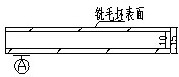
1 |
Milling the upper and lower surfaces of the blank and milling it into a 95×95×10 square |
 |
CNC vertical milling machine | Universal fixture |
Tool: Carbide end mill Ф = 16 S=1000 F=100 δ=2.5 |
Vernier caliper
|
|
2 |
Milling a through hole with a radius = 13mm in the center of the blank and milling the plum-like groove beside it |
 |
CNC vertical milling machine | Pressure iron |
Tool: Carbide end mill Ф = 16 S=1000 F=100 δ1=10 δ2=5 |
Vernier caliper
|
|
3 |
The outer contour of the blank is machined to 90×90×10 and the round radius R=8mm |
 |
CNC vertical milling machine | Universal fixture |
Tool: Carbide end mill Ф = 16 S=1000 F=100 |
Vernier caliper
|
|
4 |
A groove having a depth of 1.5 mm is milled on the bottom surface of the blank to leave four protrusions on the bottom surface. |
 |
CNC vertical milling machine | Pressure iron |
Tool: End mill Ф = 10 S=1000 F=100 δ=1.5 |
Vernier caliper
|
|
5 |
A through hole having a radius of R=8 mm is drilled in the four legs of the base to be formed. |
 |
CNC vertical milling machine |
Pressure iron |
Tool: Center drill ø8 S=1000 F=100 δ=10 |
Vernier caliper
|
2.3.6 Determine the machining allowance for each process and calculate the process dimensions and tolerances:
1. The machining allowance for the hole and the upper and lower grooves is 0.2.
2. The design requirements of the large through hole are: 260+0.052, Ra=1.6, and the edge of the hole is perpendicular to the bottom surface with a tolerance of 0.02.
The groove design next to the through hole requires:
1) The depth is 5+0.048, and the bottom edge requires a parallelism tolerance of 0.02 based on the bottom surface.
2) The width of the four corners of the groove is designed to be: 20+0.033
The four sides of the square base are designed to be 90 ± 0.05.
Design requirements for the bottom groove: 1.5mm depth, no tolerance requirements.
Four small through hole design requirements for the base:
1) The distance between adjacent holes is designed to be 70+0.03.
2) Hole design requirements: A through hole with a diameter Ф=8 is required.
2.4 CNC programming coordinate system:
The coordinate system is established with the center of the workpiece as the origin. The coordinate axis parallel to the spindle is the Z coordinate axis, and the direction of the tool away from the workpiece is the positive direction. It is perpendicular to the Z axis and parallel to the workpiece clamping plane in the X direction. When viewed in the direction of the main axial column of the tool, the tool direction is again in the +X direction. The Y axis is perpendicular to the X and Z coordinates, and the +Y direction is determined by the right hand flute method.
2.5 parts CNC machining program:
| Process | Processing program | Description |
|
1 |
N10G90G54G00Z60.000 N12S1000M03 N14X-4.480Y4.480Z60.000 N16Z50.000 N18Z22.500 N20G01Z12.500F10 N22X4.480F100 N24Y-4.480 N26X-4.480 N28Y4.480 N30X-9.480Y9.480 N32X9.480 N34Y-9.480 N36X-9.480 N38Y9.480 N40X-14.480Y14.480 N42X14.480 N44Y-14.480 N46X-14.480 N48Y14.480 N50X-19.480Y19.480 N52X19.480 N54Y-19.480 N56X-19.480 N58Y19.480 N60X-24.480Y24.480 N62X24.480 N64Y-24.480 N66X-24.480 N68Y24.480 N70X-29.480Y29.480 N72X29.480 N74Y-29.480 N76X-29.480 N78Y29.480 N80X-34.480Y34.480 N82X34.480 N84Y-34.480 N86X-34.480 N88Y34.480 N90X-39.480Y39.480 N92X39.480 N94Y-39.480 N96X-39.480 N98Y39.480 N100Z50.000F800 N102G00Z60.000 N104M05 N106M30 |
Plane area processing track Tool: Ф16(10) Tool radius = 8.000 tool radius = 0.000 Spindle speed = 1000.000 approach speed = 10.000 Cutting speed = 100.000 retraction speed = 800.000 Lower knife speed = 100.000 line connection speed = 100.000 Starting and ending height = 60.000 safe height = 50.000 Slow lower knife relative height = 10.000 Feeding method: vertical Retracting method: vertical Way of cutting: circumcision processing (from inside to outside) Draft reference: the bottom layer is the benchmark Contour parameters: compensation mode (TO) margin = 0.200, draft angle = 0.000 Island parameter: compensation mode (ON) margin = 0.000, draft angle = 0.000 Top height = 15.000 bottom height = 12.500 height per floor = 2.500 Corner transition mode: arc Processing line spacing = 5.000 Machining accuracy = 0.001 Whether to raise the knife in the area: no knife Knife cutting method: vertical The position of the lower knife point: the end point of the diagonal line or the tangent point of the spiral line Clear roots: not clear roots Island clearing roots: not clearing the roots Clear root feeding method: vertical Clear root retreat method: vertical Processing time = 15.63 minutes |
|
2 |
N10G90G54G00Z60.000 N12S1000M03 N14X5.000Y-0.000Z60.000 N16Z50.000 N18Z15.000 N20G01Z5.000F10 N22G42D10G02X5.000Y0.000I-5.000J0.000F100 N24G01Z50.000F800 N26G00Z10.000 N28G01Z0.000F10 N30G42D10G02X5.000Y0.000I-5.000J0.000F100 N32G01Z50.000F800 N34G00Z60.000 N36M05 N38S1000M03 N40X-25.000Y2.000 N42Z50.000 N44Z15.000 N46G01Z5.000F10 N48G42D10X-20.000F100 N50G03X-2.000Y20.000I0.000J18.000 N52G01Y25.000 N54G02X2.000Y25.000I2.000J0.000 N56G01Y20.000 N58G03X20.000Y2.000I18.000J-0.000 N60G01X25.000 N62G02X25.000Y-2.000I-0.000J-2.000 N64G01X20.000 N66G03X2.000Y-20.000I-0.000J-18.000 N68G01Y-25.000 N70G02X-2.000Y-25.000I-2.000J0.000 N72G01Y-20.000 N74G03X-20.000Y-2.000I-18.000J0.000 N76G01X-25.000 N78G40G02X-25.000Y2.000I0.000J2.000 N80G01Z50.000F800 N82G00Z60.000 N84M05 N86M30 |
Tool: Ф20,12(10) Spindle speed = 1000.000 approach speed = 10.000 Cutting speed = 100.000 retraction speed = 800.000 Lower knife speed = 100.000 line connection speed = 100.000 Starting and ending height = 60.000 safe height = 50.000 Slow lower knife relative height = 10.000 Feeding method: vertical Retracting method: vertical Way of walking: reciprocating Contour compensation method: TO Corner transition mode: arc Machining accuracy = 0.001 Knife = 1 Through hole: top layer height = 10.000 bottom layer height = 0.000 height per layer = 5.000 Groove: top height = 10.000 bottom height = 5.000 height per layer = 5.000 Knife cutting method: vertical The position of the lower knife point: the end point of the diagonal line or the tangent point of the spiral line Draft reference: the bottom layer is the benchmark Crossing between layers: reciprocating Line spacing definition: line spacing Machining allowance = 0.200 Processing line spacing = 5.000 Machine tool automatic compensation (G41/G42) |
|
3 |
N10G90G54G00Z60.000 N12S1000M03 N14X-53.000Y-35.000Z60.000 N16Z50.000 N18Z15.000 N20G01Z5.000F10 N22G41D10Y35.000F100 N24G02X-35.000Y53.000I18.000J-0.000 N26G01X35.000 N28G02X53.000Y35.000I-0.000J-18.000 N30G01Y-35.000 N32G02X35.000Y-53.000I-18.000J-0.000 N34G01X-35.000 N36G40G02X-53.000Y-35.000I0.000J18.000 N38G01Z50.000F800 N40G00Z10.000 N42G01Z0.000F10 N44G41D10Y35.000F100 N46G02X-35.000Y53.000I18.000J-0.000 N48G01X35.000 N50G02X53.000Y35.000I-0.000J-18.000 N52G01Y-35.000 N54G02X35.000Y-53.000I-18.000J-0.000 N56G01X-35.000 N58G40G02X-53.000Y-35.000I0.000J18.000 N60G01Z50.000F800 N62G00Z60.000 N64M05 N66M30 |
Tool: Ф16(10) Tool radius = 10.000 corner radius = 0.000 Spindle speed = 1000.000 approach speed = 10.000 Cutting speed = 100.000 retraction speed = 800.000 Lower knife speed = 100.000 line connection speed = 100.000 Starting and ending height = 60.000 safe height = 50.000 Slow lower knife relative height = 10.000 Feeding method: vertical Retracting method: vertical Way of walking: reciprocating Corner transition mode: arc Machining accuracy = 0.001 Knife = 1 Top height = 10.000 bottom height = 0.000 height per floor = 5.000 Contour draft angle = 0.000 Knife cutting method: vertical The position of the lower knife point: the end point of the diagonal line or the tangent point of the spiral line Draft reference: the bottom layer is the benchmark Crossing between layers: reciprocating Line spacing definition: line spacing Machining allowance = 0.200 Processing line spacing = 5.000 Machine tool automatic compensation (G41/G42) Processing time = 9.46 minutes |
2.6 processing track:
Machining program simulation check:
It can be simulated in the numerical control laboratory and can simulate its processing trajectory.
Summary
Through this design, the entire process of CNC machining has a comprehensive understanding. Through reading the map and reviewing the map, I have a deeper understanding of the mechanical drawings, and enhanced my ability to map, and at the same time, avoid many mistakes when drawing my own drawings;
By selecting the tool, I have a deep understanding of the characteristics of the CNC machine tool system and the NC tool material and the scope of use, and basically master the selection method of the CNC tool; After formulating the technological plan, we will further understand the six-point positioning principle, the positioning method and the types and characteristics of the positioning components and the commonly used fixtures for CNC machine tools, and have a deeper understanding of the selection principle of the machine tool-related positioning reference and the selection method of the CNC machining fixture. The principles, steps and methods for designing special fixtures; After programming the parts, I am familiar with the main contents and steps of CNC programming, programming and types, and the structure and format of the program. I have re-learned the drawing software such as CAD, CAM, Pro/E, etc., so that I have mastered the application of these kinds of software better and skillfully. At the same time, I also learned to use the automatic programming software for NC-assisted programming.


