Lathes, Turning Tool & Cylindrical Surface Turning
Summary: Taking CA6140 horizontal lathe as an example to introduce the purpose and movement of the lathe, type and structure, process range and transmission route. To provide a reference for reasonable choice of external turning tool structure and clamping method, as well as outer circle surface turning and clamping scheme.
Keywords: lathe, turning, turning the outer circumferential surface
Lathe
1.1 The use of lathes
Lathes are mainly used to machine various rotating surfaces of parts. Such as the inner and outer cylindrical surface, the inner and outer conical surfaces, the forming rotary surface and the end surface of the rotary body, some lathes can turn the threaded surface. Since most machine parts have a rotating surface and most require machining on a lathe, Therefore, the lathe is the most widely used type of machine tool in a general machine factory, accounting for about 35% to 50% of the total number of machine tools. On the lathe, in addition to the use of turning tools, it is also possible to use a variety of hole-making tools (such as drills, reamers, boring tools, etc.) for hole machining. Or using threaded tool (screw tap, screw die) for internal and external threading.
1.2 The movement of the lathe
1.2.1 Rotary motion of the workpiece:
Is the main movement of the lathe, its characteristics are higher speed, greater power consumption.
1.2.2 Tool linear movement:
It is the feed movement of the lathe that is to make the new metal layer of the blank be continuously cut in order to cut the entire machining surface. The above mentioned movement is a surface forming movement required for the lathe to form the shape of the machining surface. Turning the thread on the lathe, the rotary motion of the workpiece and the linear movement of the tool form a spiral motion, which is a compound forming motion.
1.3 Classification of Lathes
In order to adapt to different processing requirements, lathes are divided into many types. According to its structure and use,
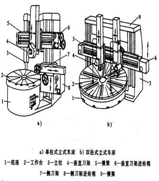
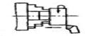
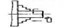
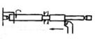
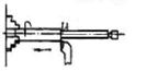
Can be divided into: horizontal lathes (Figure 2), vertical lathes (Figure 1), turret lathes, Turnback lathes, floor lathes, Hydraulic profiling and multi-knife automatic and semi-automatic lathes, Various special lathes (such as crankshaft lathes, cam lathes, etc.), CNC lathes and turning machining centers.
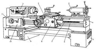
1 - bed leg, 2 - feed box, 3 - spindle box, 4 - bed saddle, 5 - medium skateboard, 6 - knife frame, 7 - rotary disc, 8 - small skateboard, 9 - tail frame, 10 - bed body 12 - optical bar, 13 - screw, 14 - slide box
1.4 Technological scope and composition of CA6140 horizontal lathe
The versatility of the CA6140 horizontal lathe is strong, but the structure of the machine tool is complex and its degree of automation is low. Auxiliary time is longer in the process, suitable for single-piece, small-batch production and repair shop.
The layout and composition of the CA6140 horizontal lathe are shown in Figure 2.
The versatility of the CA6140 horizontal lathe is strong, but the machine tool has a complex structure and a low degree of automation. The auxiliary process takes a long time in the process and is suitable for single-piece and small-batch production and repair workshops. The layout and composition of the CA6140 horizontal lathe are shown in Figure 2.
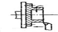
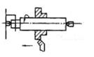
The CA6140 horizontal lathe has a wide range of processes and can be applied to the machining of various rotating surfaces, such as turning inner and outer cylindrical surfaces, conical surfaces, ring grooves and formed turning surfaces; turning end surfaces and various common threads; It can also perform Drilling, reaming, hinges, hobbing, tapping and thread die cutting. The typical surface for processing is shown in Figure 3.
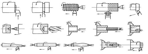
Figure 3 CA6140 Horizontal Lathe Typical surface machined
1.5 Machine Tool Drive System
Figure 4 shows the drive system of the CA6140 horizontal lathe. The upper left box in the figure indicates the spindle box of the machine tool, and the box is the main movement transmission chain from the main motor to the lathe spindle. The slip gear shifting mechanism in the transmission chain can make the spindle get different rotation speeds; The plate type friction clutch reversing mechanism allows the spindle to obtain positive and negative speeds. The lower left box indicates the feed box, and the lower right box indicates the sliding box. From the lower half of the transmission in the spindle box, to the left outer hanging wheel mechanism, the transmission element in the feed box, the screw or feed rod, and the transmission element in the sliding box constitute the feed chain from the spindle to the tool holder. The feed reversing mechanism is located in the lower part of the headstock and is used to cut left-handed or right-handed threads, and a shifting mechanism in the hanging wheel or feed box is used to decide whether to transmit motion to the lead screw or the feed rod. If it is passed to the lead screw, the opening screw nut in the lead screw and sliding box is used to transmit the motion to the tool holder to achieve the cutting screw transmission chain. If it is transmitted to the feed rod, it is transmitted to the tool post through the conversion mechanism in the feed rod and the sliding box, and a motorized feed chain is formed. The conversion mechanism in the sliding box is used to determine whether it is a longitudinal feed or a horizontal feed.
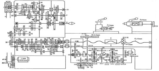
Figure 4 Transmission system diagram of CA6140 horizontal lathe
1.5.1 primary motion drive chain
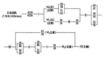 The movement is transmitted from the main motor via the V-belt drive Ф130mm/Ф230mm to the shaft I in the spindle box. The shaft I is equipped with a two-way multi-disc friction clutch M1 to rotate the spindle forward, reverse or stop. The expression of the transmission route of the main movement drive chain is shown in the left figure. It can be seen from the expression of the transmission line that the main shaft can only obtain 2×3×[(2×2-1)+1]=24 positive rotation speeds.
The spindle can obtain 3×[(2×2-1)+1]=12 reverse rotation speeds.
1.5.2 Turning Thread Drive Chain
The CA6140 lathe can turn metric, imperial, modular and radial four standard threads. It can also turn large lead, non-standard and more precise threads. These threads can be left-handed or dextral. The function of turning the thread drive chain is to obtain the lead of various threads. The conversion of the parameters is shown in Table 1.
Table 1 Pitch parameters of various standard threads And its The conversion relation of pitch and guide
The longitudinal maneuver feed of the CA6140 lathe is 64 stages. Wherein, when the feed movement is performed by the main shaft through the normal pitch metric system screw transmission route, a normal feed amount of 0.08 to 1.22 mm/r 32 levels can be obtained; When the feed motion is from the spindle through the normal pitch and inch thread drive line, a larger feed rate of 0.86 to 1.59mm/r 8 can be obtained;If the enlarged pitch mechanism is switched on, and the metric thread drive line is selected, and u-number = 1/8, 0.028-0.054mm/r8-level fine feed rate for high-speed precision turning can be obtained. By connecting the enlarged pitch mechanism and adopting the inch thread drive line and appropriately adjusting the doubler mechanism, the increased feed amount for the range of 1.71 to 6.33mm/r 16 for heavy cutting or wide edge finishing can be obtained.
It can be seen from the analysis that when the transmission paths in the headstock and the feed box are the same, the resulting horizontal maneuvering magnitude is the same as the longitudinal direction, and the horizontal feed f horizontal = 1/2f vertical.
This is because infeed is often used for grooving or cutting.
1.5.4 Tool Holder Quickly Moves the Drive Chain
The rapid movement of the tool holder is driven by a fast motor (0.25kw, 2800r/min) mounted in a sliding box. After pressing the fast-moving button to start the fast motor, the two-way clutches M8 and M9 in the sliding box control their vertical and horizontal two-way rapid movements.
When the tool holder moves quickly, it is not necessary to disengage the power feed chain. An overrunning clutch M6 is provided between the gear 56 and the shaft XX to ensure that the feed rod and the quick motor simultaneously transmit to the shaft XX without interfering with each other.
2. The structure of the turning tool
According to the structure, turning tools can be divided into integral type, welding type, machine clamping regrinding type and machine clamping transposition type.
Integral turning tool is the cutting part of the turning tool, and the clamping part is made of the same material, such as high-speed steel turning tool with small size.
Welded turning tool is based on the shape and size of the blade in the carbon steel arbor (usually 45 steel), after milling the sipe, the brazed carbide insert is brazed in the sipe, and then the required geometric parameters are sharpened. The welding type turning tool has the advantages of simple structure, compactness, good rigidity and flexibility, and can easily sharpen the required angle according to the cutting requirements, so it is widely used. However, the high-temperature brazed carbide inserts are prone to stress and cracks, and the cutting performance is reduced. The arbors cannot be reused and the waste is large.
The blades and arbors of the Regrinding tool are two separate, separate components. The clamping elements are used to fasten them together during cutting, which can improve the cutting performance of the tool due to the avoidance of defects caused by welding, and the tool bar can be used multiple times.
Clamps The indexable turning tools are polygonal blades that will be pressed with reasonable geometric parameters, chipbreakers, and several cutting edges.
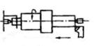
A tool structure that is clamped on a standard shank to achieve cutting with a mechanical clamping method. When one of the cutting edges of the blade is blunt, the clamping element is released and the blade is indexed for another new cutting edge and can be used again. Compared with the welding tool, the indexable turning tool has the advantages of high cutting efficiency, long blade life and low tool consumption. The arbor of an indexable turning tool can be reused, saving the shank material. Arbors and inserts can be standardized and serialized, with the use of tool management. Figure 5 shows the structure of a common turning tool.
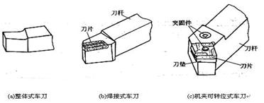
Figure 5 Schematic diagram of a common turning tool
3.Selection and clamping of outer circle cutter
Cylindrical turning tools should be selected according to the cylindrical surface machining plan. The roughing outer circle requires a high strength of the outer rough turning tool, which can keep the cutter head firm in the case of a large depth of cut or a fast cutting speed. Finish turning The outer circle requires that the outer turning cutter blade is sharp and smooth. As shown in Figure 6, Main deflection angle Кr = 75 ° external turning tool head high strength, often used in production for the outer rough turning tool; Lead angle Кr = 45 ° elbow turning tool, easy to use, but also the car face and chamfer, but because of its declination angle К'r large workpiece surface roughness, not suitable for finishing; The external turning tool with a primary angle of Кr=90° can be used with a roughing or finish turning, and can also be turned with an outer circle and an elongated shaft with vertical steps.
The mounting height of the turning tool on the tool holder shall generally be such that the height of the tool tip and the axis of rotation of the workpiece are equal, and the top of the tail frame may be used as a standard when installing. Or a mark on the end of the workpiece, you can know the location of the axis, the adjustment and installation of the turning tool.
The position of the turning tool on the tool holder should generally be perpendicular to the axis of rotation of the workpiece, otherwise it will cause the change of the primary angle Кr. It may also cause the tool tip to penetrate into the machined surface of the workpiece or affect the surface roughness quality.
4. Turning outer circumferential surface
Turning circle is one of the most common and basic turning methods. Its main form is shown in Figure 6. Turning the outer circle can be generally divided into rough cars, rough cars, semi-finish cars, fine cars and fine cars. The machining accuracy and surface roughness that can be achieved by various turning programs are not the same, and must be reasonably selected. See Table 2 for details.
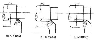
Figure 6 The formation of the turning of the outer circle
Table 2 The machining accuracy and surface roughness achieved by various turning solutions
5. The clamping method of the workpiece in the outer circle turning
The most common article clamping method in cylindrical turning is shown in Table 3.
Table 3 The most common turning clamping method
Keywords: lathe, turning, turning the outer circumferential surface
Lathe
1.1 The use of lathes
Lathes are mainly used to machine various rotating surfaces of parts. Such as the inner and outer cylindrical surface, the inner and outer conical surfaces, the forming rotary surface and the end surface of the rotary body, some lathes can turn the threaded surface. Since most machine parts have a rotating surface and most require machining on a lathe, Therefore, the lathe is the most widely used type of machine tool in a general machine factory, accounting for about 35% to 50% of the total number of machine tools. On the lathe, in addition to the use of turning tools, it is also possible to use a variety of hole-making tools (such as drills, reamers, boring tools, etc.) for hole machining. Or using threaded tool (screw tap, screw die) for internal and external threading.
1.2 The movement of the lathe
1.2.1 Rotary motion of the workpiece:
Is the main movement of the lathe, its characteristics are higher speed, greater power consumption.
1.2.2 Tool linear movement:
It is the feed movement of the lathe that is to make the new metal layer of the blank be continuously cut in order to cut the entire machining surface. The above mentioned movement is a surface forming movement required for the lathe to form the shape of the machining surface. Turning the thread on the lathe, the rotary motion of the workpiece and the linear movement of the tool form a spiral motion, which is a compound forming motion.
1.3 Classification of Lathes
In order to adapt to different processing requirements, lathes are divided into many types. According to its structure and use,
Can be divided into: horizontal lathes (Figure 2), vertical lathes (Figure 1), turret lathes, Turnback lathes, floor lathes, Hydraulic profiling and multi-knife automatic and semi-automatic lathes, Various special lathes (such as crankshaft lathes, cam lathes, etc.), CNC lathes and turning machining centers.
1 - bed leg, 2 - feed box, 3 - spindle box, 4 - bed saddle, 5 - medium skateboard, 6 - knife frame, 7 - rotary disc, 8 - small skateboard, 9 - tail frame, 10 - bed body 12 - optical bar, 13 - screw, 14 - slide box
The versatility of the CA6140 horizontal lathe is strong, but the structure of the machine tool is complex and its degree of automation is low. Auxiliary time is longer in the process, suitable for single-piece, small-batch production and repair shop.
The layout and composition of the CA6140 horizontal lathe are shown in Figure 2.
The versatility of the CA6140 horizontal lathe is strong, but the machine tool has a complex structure and a low degree of automation. The auxiliary process takes a long time in the process and is suitable for single-piece and small-batch production and repair workshops. The layout and composition of the CA6140 horizontal lathe are shown in Figure 2.
The CA6140 horizontal lathe has a wide range of processes and can be applied to the machining of various rotating surfaces, such as turning inner and outer cylindrical surfaces, conical surfaces, ring grooves and formed turning surfaces; turning end surfaces and various common threads; It can also perform Drilling, reaming, hinges, hobbing, tapping and thread die cutting. The typical surface for processing is shown in Figure 3.
Figure 3 CA6140 Horizontal Lathe Typical surface machined
Figure 4 shows the drive system of the CA6140 horizontal lathe. The upper left box in the figure indicates the spindle box of the machine tool, and the box is the main movement transmission chain from the main motor to the lathe spindle. The slip gear shifting mechanism in the transmission chain can make the spindle get different rotation speeds; The plate type friction clutch reversing mechanism allows the spindle to obtain positive and negative speeds. The lower left box indicates the feed box, and the lower right box indicates the sliding box. From the lower half of the transmission in the spindle box, to the left outer hanging wheel mechanism, the transmission element in the feed box, the screw or feed rod, and the transmission element in the sliding box constitute the feed chain from the spindle to the tool holder. The feed reversing mechanism is located in the lower part of the headstock and is used to cut left-handed or right-handed threads, and a shifting mechanism in the hanging wheel or feed box is used to decide whether to transmit motion to the lead screw or the feed rod. If it is passed to the lead screw, the opening screw nut in the lead screw and sliding box is used to transmit the motion to the tool holder to achieve the cutting screw transmission chain. If it is transmitted to the feed rod, it is transmitted to the tool post through the conversion mechanism in the feed rod and the sliding box, and a motorized feed chain is formed. The conversion mechanism in the sliding box is used to determine whether it is a longitudinal feed or a horizontal feed.
Figure 4 Transmission system diagram of CA6140 horizontal lathe
1.5.1 primary motion drive chain
The movement is transmitted from the main motor via the V-belt drive Ф130mm/Ф230mm to the shaft I in the spindle box. The shaft I is equipped with a two-way multi-disc friction clutch M1 to rotate the spindle forward, reverse or stop. The expression of the transmission route of the main movement drive chain is shown in the left figure. It can be seen from the expression of the transmission line that the main shaft can only obtain 2×3×[(2×2-1)+1]=24 positive rotation speeds.The spindle can obtain 3×[(2×2-1)+1]=12 reverse rotation speeds.
1.5.2 Turning Thread Drive Chain
The CA6140 lathe can turn metric, imperial, modular and radial four standard threads. It can also turn large lead, non-standard and more precise threads. These threads can be left-handed or dextral. The function of turning the thread drive chain is to obtain the lead of various threads. The conversion of the parameters is shown in Table 1.
Table 1 Pitch parameters of various standard threads And its The conversion relation of pitch and guide
|
Thread type |
Pitch parameters | Pitch/mm | Lead/mm |
| Metric system | Pitch P/mm | P=P | L=KP |
| Modulus system | Modulus m/mm | Pm=πm | Lm=KPm=Kπm |
| British system | Number of teeth per inch a (teeth/in) | Pa=25.4/a | La=K Pa =25.4K/a |
| Diameter abstinence | Diameter DP (dentine/in) | PDP=25.4 π/DP | LDP=KPDP=25.4Kπ/DP |
1.5.3 Longitudinal and lateral maneuvering drive chains
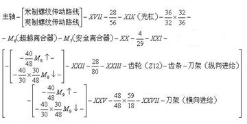
Longitudinal feed is generally used for cylindrical turning, while transverse feed is used for face turning. In order to reduce the wear of the lead screw and to facilitate the manipulation, the motor feed is driven by the feed rod via the sliding box, and the expression of the transmission route is as shown in the left figure.The longitudinal maneuver feed of the CA6140 lathe is 64 stages. Wherein, when the feed movement is performed by the main shaft through the normal pitch metric system screw transmission route, a normal feed amount of 0.08 to 1.22 mm/r 32 levels can be obtained; When the feed motion is from the spindle through the normal pitch and inch thread drive line, a larger feed rate of 0.86 to 1.59mm/r 8 can be obtained;If the enlarged pitch mechanism is switched on, and the metric thread drive line is selected, and u-number = 1/8, 0.028-0.054mm/r8-level fine feed rate for high-speed precision turning can be obtained. By connecting the enlarged pitch mechanism and adopting the inch thread drive line and appropriately adjusting the doubler mechanism, the increased feed amount for the range of 1.71 to 6.33mm/r 16 for heavy cutting or wide edge finishing can be obtained.
It can be seen from the analysis that when the transmission paths in the headstock and the feed box are the same, the resulting horizontal maneuvering magnitude is the same as the longitudinal direction, and the horizontal feed f horizontal = 1/2f vertical.
This is because infeed is often used for grooving or cutting.
1.5.4 Tool Holder Quickly Moves the Drive Chain
The rapid movement of the tool holder is driven by a fast motor (0.25kw, 2800r/min) mounted in a sliding box. After pressing the fast-moving button to start the fast motor, the two-way clutches M8 and M9 in the sliding box control their vertical and horizontal two-way rapid movements.
When the tool holder moves quickly, it is not necessary to disengage the power feed chain. An overrunning clutch M6 is provided between the gear 56 and the shaft XX to ensure that the feed rod and the quick motor simultaneously transmit to the shaft XX without interfering with each other.
2. The structure of the turning tool
According to the structure, turning tools can be divided into integral type, welding type, machine clamping regrinding type and machine clamping transposition type.
Integral turning tool is the cutting part of the turning tool, and the clamping part is made of the same material, such as high-speed steel turning tool with small size.
Welded turning tool is based on the shape and size of the blade in the carbon steel arbor (usually 45 steel), after milling the sipe, the brazed carbide insert is brazed in the sipe, and then the required geometric parameters are sharpened. The welding type turning tool has the advantages of simple structure, compactness, good rigidity and flexibility, and can easily sharpen the required angle according to the cutting requirements, so it is widely used. However, the high-temperature brazed carbide inserts are prone to stress and cracks, and the cutting performance is reduced. The arbors cannot be reused and the waste is large.
The blades and arbors of the Regrinding tool are two separate, separate components. The clamping elements are used to fasten them together during cutting, which can improve the cutting performance of the tool due to the avoidance of defects caused by welding, and the tool bar can be used multiple times.
Clamps The indexable turning tools are polygonal blades that will be pressed with reasonable geometric parameters, chipbreakers, and several cutting edges.
A tool structure that is clamped on a standard shank to achieve cutting with a mechanical clamping method. When one of the cutting edges of the blade is blunt, the clamping element is released and the blade is indexed for another new cutting edge and can be used again. Compared with the welding tool, the indexable turning tool has the advantages of high cutting efficiency, long blade life and low tool consumption. The arbor of an indexable turning tool can be reused, saving the shank material. Arbors and inserts can be standardized and serialized, with the use of tool management. Figure 5 shows the structure of a common turning tool.
Figure 5 Schematic diagram of a common turning tool
3.Selection and clamping of outer circle cutter
Cylindrical turning tools should be selected according to the cylindrical surface machining plan. The roughing outer circle requires a high strength of the outer rough turning tool, which can keep the cutter head firm in the case of a large depth of cut or a fast cutting speed. Finish turning The outer circle requires that the outer turning cutter blade is sharp and smooth. As shown in Figure 6, Main deflection angle Кr = 75 ° external turning tool head high strength, often used in production for the outer rough turning tool; Lead angle Кr = 45 ° elbow turning tool, easy to use, but also the car face and chamfer, but because of its declination angle К'r large workpiece surface roughness, not suitable for finishing; The external turning tool with a primary angle of Кr=90° can be used with a roughing or finish turning, and can also be turned with an outer circle and an elongated shaft with vertical steps.
The mounting height of the turning tool on the tool holder shall generally be such that the height of the tool tip and the axis of rotation of the workpiece are equal, and the top of the tail frame may be used as a standard when installing. Or a mark on the end of the workpiece, you can know the location of the axis, the adjustment and installation of the turning tool.
The position of the turning tool on the tool holder should generally be perpendicular to the axis of rotation of the workpiece, otherwise it will cause the change of the primary angle Кr. It may also cause the tool tip to penetrate into the machined surface of the workpiece or affect the surface roughness quality.
4. Turning outer circumferential surface
Turning circle is one of the most common and basic turning methods. Its main form is shown in Figure 6. Turning the outer circle can be generally divided into rough cars, rough cars, semi-finish cars, fine cars and fine cars. The machining accuracy and surface roughness that can be achieved by various turning programs are not the same, and must be reasonably selected. See Table 2 for details.
Figure 6 The formation of the turning of the outer circle
| No. | processing method | Economic accuracy (tolerance grade) | Economic roughness Ra value/μm | Range of use |
| 1 | rough turn | IT13~IT11 | 50~12.5 | Suitable for various metals other than hardened steel |
| 2 | rough turn- Half finished turning | IT10~IT8 | 6.3~3.2 | |
| 3 | rough turn- Half finished turning-finished turning | IT8~IT7 | 1.6~0.8 | |
| 4 | rough turn- Half finished turning-finished turning- fine turning(Diamond turning) | IT7~IT6 | 0.4~0.025 | Mainly used for high-demand non-ferrous metals |
The most common article clamping method in cylindrical turning is shown in Table 3.
Table 3 The most common turning clamping method
| Name | Clipping diagram | Clamping Features | application |
| Three claw chuck |
 |
The three claw can move at the same time, automatic centering, fast and convenient clamping. | The ratio of length to diameter is less than 4, the cross section is round, the middle and small parts processing of hexagonal body |
| Four claw chuck |
 |
The four jaws can be moved separately, and the workpiece needs to be corrected. | The aspect ratio is less than 4, Larger, heavier workpieces with square, oval cross-sections |
| Flower Disk |
 |
There are multiple grooves and T grooves on the disc, which are clamped by screws and platen. | Processing irregular shape of the workpiece, and the positioning hole or cylindrical workpiece perpendicular to the base surface |
| Double top tip |
 |
Centering accuracy, clamping stability | An aspect ratio of 4 to 15, a solid shaft parts processing |
| Double top center frame |
 |
Adjustable support claws, increase the rigidity of the workpiece | Slender shaft workpiece roughing with aspect ratio greater than 15 |
| A clip with a knife frame |
 |
The claws move with the cutter without a tool mark | Semi-finishing and finishing of slender shafts with length-diameter ratio greater than 15 |
| Mandrel |
 |
To ensure the accuracy of the position of the outer circle and the end facing the inner hole | The machining of sets of parts with holes as the reference |


