The Process of Automatic Tool Change in NC Machining Center
A light gantry machining center machine tool automatic tool change process:
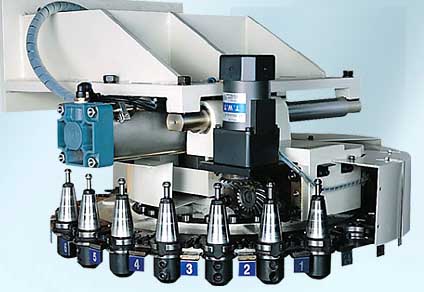
1. Lightweight Gantry Machining Center Machine Overview
The light-duty gantry machine is a table-moving, beam-fixed gantry machine with or without a tool magazine.
The machine tool consists of a bed, a column and a fixed beam to form a high-rigidity closed frame. The worktable performs longitudinal movement on the bed rail, which is an X coordinate;
The slide plate performs lateral movement on the beam guide rail, which is a Y coordinate;
The ram boring and milling head performs vertical movement on the slide rail, which is the Z coordinate. The machine tool adopts SIEMENS840DE control system, and the X, Y and Z axes of the machine tool are all CNC control axes. The spindle is driven by Siemens AC spindle motor, and the X, Y and Z three-way feed are driven by Siemens servo motor. Three-dimensional linear interpolation, two-dimensional circular interpolation and any three-axis linkage can be realized.
2. Automatic tool change control requirements
2.1 Tool magazine control
Machine tool magazine can be disk magazine, magazine capacity of 20. The spindle and the tool changer use a robot without a robot, and the tool is used to find the knife nearby, and the tool is directly changed in situ; It is also possible to use a chain tool magazine with a tool magazine capacity of 40 knives, a robot, any knife, and any tool change. The magazine disk is driven by the motor through the gear speed reduction, with positive, reverse and stop controls. In order to quickly stop the tool magazine, a power-off friction brake is added to the motor output shaft. When the stop signal is issued, the electromagnet of the brake is de-energized, so that the tool magazine stops rotating. The indexing and positioning of the rotation of the magazine disk is realized by a Markov mechanism, a zero switch and a counting switch. Each time the magazine is transferred to one location, the count switch operates once. When the magazine is turned to zero, the zero switch also acts. When the magazine is transferred to the specified location, the counting switch or the zero switch is activated. At this time, the motor is stopped and the brake is de-energized, so that the magazine is stopped and the Markov mechanism is accurately positioned at the tool change position. After the magazine is stopped, the count switch or zero switch is turned off, and an alarm should be prompted.
2.2 Pneumatic control
The protective door switch of the tool magazine and the spindle cone blow air are pneumatically controlled, and the gas source gas is processed and supplied to the cylinder. The tool magazine protection door switch is driven by a cylinder, and the control is completed by a two-position four-way dual electronically controlled reversing valve. The characteristics of the reversing valve are:
The two positions of the reversing valve are controlled by two electromagnets, and the reversing valve only needs to give the electromagnet a short electrical signal (the electrical signal waiting time is 2s) to complete the commutation. The reversing valve will change to another position only after giving a short electrical signal to the other electromagnet. The spindle cone blow is used to clean the spindle cone, and the blow is connected by a two-position three-powered shut-off valve. When the loose knife starts, the electromagnet is energized, and the cone hole is blown until the state of the loose knife is finished, the electromagnet is de-energized, and the air blow is stopped.
2.3 Spindle broach control
The main shaft is equipped with a tool automatic tensioning mechanism, which is tensioned by a disc spring and hydraulically released. The tightening and loosening of the tool is controlled by a two-position four-way solenoid valve. The broach mechanism is divided into a knife, a knife, and a knife. The three states are monitored by three contactless sensor switches.
The tightening and loosening of the tool can be controlled by commands or by buttons on the operator panel. The release and tension of the tool should be displayed on the panel. The rotation of the spindle and the tightening and loosening action of the tool are interlocked.
3. Markov agencies
Tool magazine operation process The tool magazine of this machining center is composed of Markov mechanism tool magazine disk, zero position switch, counting switch, tool magazine door switch valve, travel switch and spindle air blowing valve. The automatic tool change of the Markov mechanism tool magazine is to move the spindle to the tool magazine, and use the loose knives of the spindle to directly grab the knife and return the knife on the tool magazine. Slow movement is required when approaching the magazine disk and leaving the magazine disk to avoid accidents caused by collisions with the tool magazine or the tool. In other locations, fast movement is required to save time. The movement of the magazine includes three processes: the spindle gripper, the spindle return knife and the spindle tool change. Several points to which the spindle will move, and S1 to S14 indicate the process of ram and slide movement. The three processes of spindle grabber, spindle return knife and spindle tool change can be graphically analyzed.
3.1 Spindle grabbing process
The spindle gripper is a knife that requires a spindle without a knife to grab the cutter head. The action is that the Y-axis moves laterally to the top of the magazine, and the Z-axis moves down to the tool position and grabs the knife. The Y axis moves laterally away from the magazine (the contents of the brackets are a description of the Y and Z axis actions):
S1 (Z axis to P0, fast) → S2 (Y axis to P1, fast) → Spindle orientation, the first soft limit takes effect, the magazine door opens →S8 (Y axis to P2, fast) → Spindle loose knife → S7 (Z axis to P3, fast) →S6 (Z-axis to P4, slow speed) →Spindle tightening knife →S12 (Y axis to P5, slow speed) →S13 (Y axis to P6, fast) →S14 (Z-axis to P1, fast) → The second software limit is valid, the spindle orientation is canceled, and the magazine door is closed.
3.2 Spindle returning process
The spindle returning knife is to return the knife on the spindle to the original position on the tool magazine. The action is that the Y axis moves laterally to the tool position and the knife is released. Z moves away from the tool to the top of the magazine, and the Y axis leaves the magazine laterally:
S1 (Z axis to P0, fast) →S2 (Y axis to P1, fast) → Spindle orientation, the first soft limit takes effect →S3 (Z-axis to P6, fast)→Magazine door open →S4 (Y axis to P5, fast) → S5 (Y axis to P4, slow speed) →Spindle loose knife →S11 (Z-axis to P3, slow speed) →S10 (Z-axis to P2, fast) →S9 (Y axis to P1, fast) → The second software limit is valid, the spindle orientation is canceled, the spindle is tightened, and the magazine door is closed.
3.3 Spindle tool change process
Spindle tool change is required to return the knife on the spindle back to the original tool position on the tool magazine, and then grab another knife on the tool magazine. The action is that the Y-axis moves laterally to reach the tool location and the knife is released. Z moves away from the tool to the top of the magazine, the tool magazine rotates to find the knife, and after the Z axis moves down to the tool position and grabs the knife, the Y axis moves laterally away from the magazine:
S1 (Z axis to P0, fast) →S2 (Y axis to P1, fast) → Spindle orientation, the first soft limit takes effect →S3 (Z-axis to P6, fast) →Knife door open →S4 (Y-axis to P5, fast) →S5 (Y axis to P4, slow speed) →Spindle loose knife →S11 (Z-axis to P3, slow speed) →S10 (Z-axis to P2, fast) →The tool magazine is rotated, and the tool magazine is looking for a knife. →S7 (Z-axis to P3, fast) →S6 (Z-axis to P4, slow speed) →Spindle tightening knife →S12 (Y axis to P5, slow speed) →S13 (Y axis to P6, fast) →S14 (Z-axis to P1, fast) → The second software limit is valid, the spindle orientation is canceled, and the magazine door is closed.
1. Processing center I/O point arrangement
1.1 Input point arrangement I33.2:
The spindle is in place with the knife in place (upper position),
I33.3: spindle tightening knife in place switch (median),
I33.4: Spindle loose knife in place switch (lower position),
I36.3: Spindle release button switch is pressed, I36.4: Spindle tight knife button switch is pressed, I62.0: Tool magazine ATC is effective,
I62.1: Tool magazine ATC is invalid,
I62.2: The magazine is jogging,
I62.3: The tool magazine returns to zero,
I62.4: The tool magazine is rotating forward,
I62.5: The tool magazine is reversed,
I62.7: magazine count,
I63.0: Tool magazine zero,
I63.1: The magazine door is open,
I63.2: Tool magazine door closed,
I63.3: Tool magazine motor monitoring,
I63.4: Tool magazine lock.
1.2 output point arrangement
Q49.0: Spindle loose-knife valve,
Q49.3: The spindle is loose,
Q56.0: ARC is valid for the tool magazine,
Q56.1: The magazine is jogging,
Q56.2: The tool magazine motor is rotating forward.
Q56.3: The tool magazine motor is reversed.
Q56.4: Tool magazine brake,
Q56.5: The magazine door is opened,
Q56.6: Tool magazine door closing valve,
Q56.7: Spindle blow valve.
2. Program function block arrangement instructions
FC51: Spindle loose broach,
FC66: Ma's tool magazine T code processing,
FC67: Markov tool magazine M code processing,
FC68: Comprehensive processing of Markov's tool magazine.
3.PLC program debugging instructions
When the tool magazine is commissioned, it is necessary to perform single-step debugging on each electrical component to ensure that each electrical component can work normally; Then, according to the knife, knife change, knife return and other actions, manual execution of all actions is performed to check the execution of the program; Finally, the T and M commands can be used to perform continuous automatic execution of the program in the automatic mode, so that the tool magazine can operate normally.
Conclusion
Our ATC has achieved good control and operational requirements by running tests on multiple products in the enterprise. Because the principle and experience of ATC are similar, there are certain reference functions for different types of CNC machine tools.
1. Lightweight Gantry Machining Center Machine Overview
The light-duty gantry machine is a table-moving, beam-fixed gantry machine with or without a tool magazine.
The machine tool consists of a bed, a column and a fixed beam to form a high-rigidity closed frame. The worktable performs longitudinal movement on the bed rail, which is an X coordinate;
The slide plate performs lateral movement on the beam guide rail, which is a Y coordinate;
The ram boring and milling head performs vertical movement on the slide rail, which is the Z coordinate. The machine tool adopts SIEMENS840DE control system, and the X, Y and Z axes of the machine tool are all CNC control axes. The spindle is driven by Siemens AC spindle motor, and the X, Y and Z three-way feed are driven by Siemens servo motor. Three-dimensional linear interpolation, two-dimensional circular interpolation and any three-axis linkage can be realized.
2. Automatic tool change control requirements
2.1 Tool magazine control
Machine tool magazine can be disk magazine, magazine capacity of 20. The spindle and the tool changer use a robot without a robot, and the tool is used to find the knife nearby, and the tool is directly changed in situ; It is also possible to use a chain tool magazine with a tool magazine capacity of 40 knives, a robot, any knife, and any tool change. The magazine disk is driven by the motor through the gear speed reduction, with positive, reverse and stop controls. In order to quickly stop the tool magazine, a power-off friction brake is added to the motor output shaft. When the stop signal is issued, the electromagnet of the brake is de-energized, so that the tool magazine stops rotating. The indexing and positioning of the rotation of the magazine disk is realized by a Markov mechanism, a zero switch and a counting switch. Each time the magazine is transferred to one location, the count switch operates once. When the magazine is turned to zero, the zero switch also acts. When the magazine is transferred to the specified location, the counting switch or the zero switch is activated. At this time, the motor is stopped and the brake is de-energized, so that the magazine is stopped and the Markov mechanism is accurately positioned at the tool change position. After the magazine is stopped, the count switch or zero switch is turned off, and an alarm should be prompted.
2.2 Pneumatic control
The protective door switch of the tool magazine and the spindle cone blow air are pneumatically controlled, and the gas source gas is processed and supplied to the cylinder. The tool magazine protection door switch is driven by a cylinder, and the control is completed by a two-position four-way dual electronically controlled reversing valve. The characteristics of the reversing valve are:
The two positions of the reversing valve are controlled by two electromagnets, and the reversing valve only needs to give the electromagnet a short electrical signal (the electrical signal waiting time is 2s) to complete the commutation. The reversing valve will change to another position only after giving a short electrical signal to the other electromagnet. The spindle cone blow is used to clean the spindle cone, and the blow is connected by a two-position three-powered shut-off valve. When the loose knife starts, the electromagnet is energized, and the cone hole is blown until the state of the loose knife is finished, the electromagnet is de-energized, and the air blow is stopped.
2.3 Spindle broach control
The main shaft is equipped with a tool automatic tensioning mechanism, which is tensioned by a disc spring and hydraulically released. The tightening and loosening of the tool is controlled by a two-position four-way solenoid valve. The broach mechanism is divided into a knife, a knife, and a knife. The three states are monitored by three contactless sensor switches.
The tightening and loosening of the tool can be controlled by commands or by buttons on the operator panel. The release and tension of the tool should be displayed on the panel. The rotation of the spindle and the tightening and loosening action of the tool are interlocked.
3. Markov agencies
Tool magazine operation process The tool magazine of this machining center is composed of Markov mechanism tool magazine disk, zero position switch, counting switch, tool magazine door switch valve, travel switch and spindle air blowing valve. The automatic tool change of the Markov mechanism tool magazine is to move the spindle to the tool magazine, and use the loose knives of the spindle to directly grab the knife and return the knife on the tool magazine. Slow movement is required when approaching the magazine disk and leaving the magazine disk to avoid accidents caused by collisions with the tool magazine or the tool. In other locations, fast movement is required to save time. The movement of the magazine includes three processes: the spindle gripper, the spindle return knife and the spindle tool change. Several points to which the spindle will move, and S1 to S14 indicate the process of ram and slide movement. The three processes of spindle grabber, spindle return knife and spindle tool change can be graphically analyzed.
3.1 Spindle grabbing process
The spindle gripper is a knife that requires a spindle without a knife to grab the cutter head. The action is that the Y-axis moves laterally to the top of the magazine, and the Z-axis moves down to the tool position and grabs the knife. The Y axis moves laterally away from the magazine (the contents of the brackets are a description of the Y and Z axis actions):
S1 (Z axis to P0, fast) → S2 (Y axis to P1, fast) → Spindle orientation, the first soft limit takes effect, the magazine door opens →S8 (Y axis to P2, fast) → Spindle loose knife → S7 (Z axis to P3, fast) →S6 (Z-axis to P4, slow speed) →Spindle tightening knife →S12 (Y axis to P5, slow speed) →S13 (Y axis to P6, fast) →S14 (Z-axis to P1, fast) → The second software limit is valid, the spindle orientation is canceled, and the magazine door is closed.
3.2 Spindle returning process
The spindle returning knife is to return the knife on the spindle to the original position on the tool magazine. The action is that the Y axis moves laterally to the tool position and the knife is released. Z moves away from the tool to the top of the magazine, and the Y axis leaves the magazine laterally:
S1 (Z axis to P0, fast) →S2 (Y axis to P1, fast) → Spindle orientation, the first soft limit takes effect →S3 (Z-axis to P6, fast)→Magazine door open →S4 (Y axis to P5, fast) → S5 (Y axis to P4, slow speed) →Spindle loose knife →S11 (Z-axis to P3, slow speed) →S10 (Z-axis to P2, fast) →S9 (Y axis to P1, fast) → The second software limit is valid, the spindle orientation is canceled, the spindle is tightened, and the magazine door is closed.
3.3 Spindle tool change process
Spindle tool change is required to return the knife on the spindle back to the original tool position on the tool magazine, and then grab another knife on the tool magazine. The action is that the Y-axis moves laterally to reach the tool location and the knife is released. Z moves away from the tool to the top of the magazine, the tool magazine rotates to find the knife, and after the Z axis moves down to the tool position and grabs the knife, the Y axis moves laterally away from the magazine:
S1 (Z axis to P0, fast) →S2 (Y axis to P1, fast) → Spindle orientation, the first soft limit takes effect →S3 (Z-axis to P6, fast) →Knife door open →S4 (Y-axis to P5, fast) →S5 (Y axis to P4, slow speed) →Spindle loose knife →S11 (Z-axis to P3, slow speed) →S10 (Z-axis to P2, fast) →The tool magazine is rotated, and the tool magazine is looking for a knife. →S7 (Z-axis to P3, fast) →S6 (Z-axis to P4, slow speed) →Spindle tightening knife →S12 (Y axis to P5, slow speed) →S13 (Y axis to P6, fast) →S14 (Z-axis to P1, fast) → The second software limit is valid, the spindle orientation is canceled, and the magazine door is closed.
two, Ma's tool magazine automatic control program description
According to the automatic tool change control requirements and the action process, the PLC is programmed to make the ATC work normally.1. Processing center I/O point arrangement
1.1 Input point arrangement I33.2:
The spindle is in place with the knife in place (upper position),
I33.3: spindle tightening knife in place switch (median),
I33.4: Spindle loose knife in place switch (lower position),
I36.3: Spindle release button switch is pressed, I36.4: Spindle tight knife button switch is pressed, I62.0: Tool magazine ATC is effective,
I62.1: Tool magazine ATC is invalid,
I62.2: The magazine is jogging,
I62.3: The tool magazine returns to zero,
I62.4: The tool magazine is rotating forward,
I62.5: The tool magazine is reversed,
I62.7: magazine count,
I63.0: Tool magazine zero,
I63.1: The magazine door is open,
I63.2: Tool magazine door closed,
I63.3: Tool magazine motor monitoring,
I63.4: Tool magazine lock.
1.2 output point arrangement
Q49.0: Spindle loose-knife valve,
Q49.3: The spindle is loose,
Q56.0: ARC is valid for the tool magazine,
Q56.1: The magazine is jogging,
Q56.2: The tool magazine motor is rotating forward.
Q56.3: The tool magazine motor is reversed.
Q56.4: Tool magazine brake,
Q56.5: The magazine door is opened,
Q56.6: Tool magazine door closing valve,
Q56.7: Spindle blow valve.
2. Program function block arrangement instructions
FC51: Spindle loose broach,
FC66: Ma's tool magazine T code processing,
FC67: Markov tool magazine M code processing,
FC68: Comprehensive processing of Markov's tool magazine.
3.PLC program debugging instructions
When the tool magazine is commissioned, it is necessary to perform single-step debugging on each electrical component to ensure that each electrical component can work normally; Then, according to the knife, knife change, knife return and other actions, manual execution of all actions is performed to check the execution of the program; Finally, the T and M commands can be used to perform continuous automatic execution of the program in the automatic mode, so that the tool magazine can operate normally.
Conclusion
Our ATC has achieved good control and operational requirements by running tests on multiple products in the enterprise. Because the principle and experience of ATC are similar, there are certain reference functions for different types of CNC machine tools.


