Crankshaft Processing Technology
1.1.1 Basic Features of Numerical Control Processing
As CNC machining adopts computer control system and CNC machine tools, CNC machining has features such as high degree of automation, high precision, stable quality, high generation efficiency, short cycle time, and high equipment use cost. In the numerical control processing technology also has some differences with the ordinary processing technology, and thus has its own characteristics.
When using ordinary machine tools, many specific process problems, such as the division and arrangement of the work step, the geometry and size of the tool, the tool path, machining allowance, cutting amount, etc. To a large extent, the operator considers and decides based on actual experience and habits. It is generally not necessary for the craftsman to make excessive regulations when designing the process specification, and the dimensional accuracy of the parts can also be guaranteed by the trial cut.
When CNC machining is used, all process problems must be designed and arranged in advance and incorporated into the machining program. The numerical control process not only includes detailed cutting steps, but also includes the contents of the jig type, specification, cutting amount, and other special requirements, as well as the process diagrams marked with numerical control machining coordinate positions. In the automatic programming, it is more necessary to determine a variety of detailed process parameters. Because of this feature, the requirement for the correctness and rationality of the processing program is extremely high, and no one can make mistakes. Otherwise, not only can't process qualified parts, but it may lead to serious consequences.
1.1.2 Main Contents of NC Machining Process
According to the practice of CNC machining, the NC machining process mainly includes the following aspects:
1) Select the parts that are suitable for machining on CNC machine tools and determine the contents of the process;
2) Numerical control process analysis of part drawings;
3) Formulation of numerical control process routes, such as procedure division, processing sequence arrangement, benchmark selection, convergence with non-NC machining processes, etc.;
4) The design of numerical control procedures, such as work steps, tool selection, fixture positioning and installation, tool path determination, measurement, and determination of cutting amount;
5) adjust the NC machining procedure procedures, such as knife, tool compensation;
6) Assign tolerances in NC machining;
7) Handle some process instructions on CNC machine tools.
1.1.3 Reasonable Selection of CNC Machining Parts
When machining parts on CNC machine tools, there are generally two situations.
In the first case, there are parts drawings and blanks, and a CNC machine tool suitable for machining the part is selected.
The second case: Already have CNC machine tools, to choose the parts that are suitable for machining on this machine. In either case, the main factors to be considered include the material and type of the blank, the complexity of the outline shape of the part, the size, the processing accuracy, the number of parts, and the heat treatment requirements. To sum up, there are three points, that is, whether the technical requirements for parts can be guaranteed, whether it is beneficial to increase productivity, and it is economically reasonable.
According to the application practice of numerical control technology at home and abroad, CNC machine tools are usually best suited for machining parts with the following characteristics:
(1) Parts for multi-variety, low-volume production or trial production of new products;
(2) Parts with complex contours and higher requirements on machining accuracy;
(3) When processing with an ordinary machine tool, parts of expensive process equipment (tools, fixtures, and dies) are required;
(4) Parts that need to be modified many times;
(5) The valuable parts are not allowed to be scrapped during processing;
(6) Urgent parts that require the shortest production cycle.
1) Selection of processing methods
The principle of selection of the processing method is to ensure the processing accuracy and surface roughness of the machined surface. Since there are generally many processing methods for obtaining the same level of precision and surface roughness, comprehensive considerations such as the shape, size, and heat treatment requirements of the parts are required in the actual selection.
2) The principle of determining the processing plan
Partially more precise surface finishes are often achieved gradually by roughing, semi-finishing and finishing.It is not sufficient to select the corresponding final processing method for these surfaces based only on the quality requirements, but the processing plan from the blank to the final forming should also be correctly determined.
1.1.5 Division of processes and work steps
General process division has the following ways
1) Dividing process according to part loading positioning
Due to the different shape of each part, the technical requirements of each surface are also different. Therefore, when it is processed, the positioning methods are different. When the outer shape is generally processed, the inner shape is positioned; when the inner shape is processed, the outer shape is positioned. Therefore, the process can be divided according to the different positioning methods.
2) According to the coarse and fine processing division process
According to the parts of the processing accuracy, stiffness and deformation, such as Jiejie division process, according to the principle of rough, fine processing to separate the process, that is, first roughing and then finishing. Different machines or different tools can be used for machining. Usually in one installation, it is not allowed to machine the surface of a part of a part and then machine the other surface of the part.
3) Divide the process by the tool used
In order to reduce the number of tool changes, compress the idle time and reduce unnecessary positioning errors. The parts can be machined in the same manner as the tool concentrated process. That is, in one setup, the same tool can be used to machine all parts that may be machined, and then another tool can be used to process other parts. The division of work steps is mainly considered in terms of machining accuracy and efficiency. In a process it is often necessary to use different tools and cutting amounts to process different surfaces. In order to facilitate the analysis and description of more complex processes, it is subdivided into steps in the process.
In short, the division of processes and steps should be based on the specific structural characteristics of the parts, technical requirements and other comprehensive consideration.
1.1.6 Determination of processing route
In NC machining, the trajectory of the tool cutter position relative to the workpiece is called the machining path. When programming, the principle of determining the processing route is mainly the following:
1) The processing route should ensure the accuracy and surface roughness of the parts being processed, and the efficiency is high;
2) Make the numerical calculation simple to reduce the programming workload;
3) The processing route should be the shortest, which can reduce the program segment and reduce the empty knife time.
4) In addition, when determining the processing route, the machining allowance of the workpiece and the stiffness of the machine tool and the cutter must be considered. It is determined whether it is a single pass or multiple passes to complete the machining and whether to adopt climb cutting or upmilling in the milling process.
1.1.7 Editing Error and Its Control
One of the outstanding features of CNC machine tools is that the machining accuracy of the parts is not only formed during the machining process, but also formed at the pre-processing stage of the machining. Errors in the programming phase are unavoidable. This is due to the principle of program control itself. In the programming stage, the information on the drawings is converted into a form acceptable to the control system.
Three types of errors will occur: approximate calculation error, interpolation error, and size rounding error.
In the point control processing, the programmed error contains a round of error in the size and directly affects the dimensional accuracy of the hole position.In the contour control processing, the interpolation accuracy is mainly influenced by the accuracy of the contour processing, and the impact of the size rounding error is secondary. Therefore, the general programmed error refers to the interpolation error.
Because there are errors in the control system and the drive system, part positioning error, tool error, tool wear error, workpiece deformation error, etc.
Therefore, only a small part of the tolerances given on the part drawings allow the errors to be assigned during the programming process. In general, the allowable programming error is equal to 0.1 to 0.2 of the part tolerance.
1.1.8 processing instructions in the process of processing
The operation of machining parts on a CNC machine must be specified in advance in the program using instructions. It is automatically implemented by the machine during processing. We call such instructions as technological instructions.
There are international standards for such instructions, namely, the preparation of functional instructions G auxiliary function instructions M two categories. In the preparation of processing procedures, it must be properly selected and handled according to the manual.
2.1.9 Selection of Material for Crankshaft
At present, the automotive engine crankshaft materials are two types of ductile iron and steel.
Due to the good cutting performance of spheroidal graphite cast iron, an ideal structure shape can be obtained. As with the steel crankshaft, various heat treatment and surface hardening treatments can be performed to improve the fatigue strength, hardness, and wear resistance of the crankshaft. The cost of the ductile iron crankshaft is only about 1/3 of the cost of the quenched and tempered steel crankshaft, so the ductile iron crankshaft has been widely used at home and abroad.
According to statistical data, the percentage of ductile iron used in automotive engine crankshafts is 90% in the United States, 85% in the United Kingdom, and 60% in Japan. In addition, Germany, Belgium and other countries have also adopted ductile iron materials in large quantities. The use of nodular cast iron crankshafts in China is even more pronounced. More than 85% of medium and small power crankshafts are made of ductile iron. For high-power automotive diesel engine crankshafts, forged steel crankshafts have a high overall mechanical performance.
Many high-strength medium-high-speed, high-power, four-stroke diesel engines use forged crankshafts without exception. Engines with a displacement of 1.6 L or more also use steel forged crankshafts.
Drawing on domestic and foreign experience, combined with the actual crankshaft design (small crankshaft), the crankshaft is made of ductile iron and the blank is cast.
1.1.10 Preparation of Process Materials, Tools and Fixtures
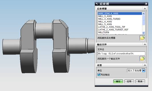
The preparation of the program is only the first step. After the program is verified, the next step is the preparation of the machining material and the tools and fixtures. How well this step is done will directly affect the ultimate effect of CNC operation.
Due to the different shapes and technical requirements of the parts during machining, different types of tools are selected for machining. For example, when machining triangular threads, triangle thread turning tools must be selected. When processing arcs, arcs must be selected to be either sharp knives for machining. A reasonable choice of machining tools is the basic guarantee for machining a good part.
The selection of the fixture is relatively simple, such as processing aluminum sticks and paraffin sticks on a CNC lathe, and aluminum sticks and paraffin sticks can be clamped directly by a three-jaw self-centering chuck;
When machining on a milling machine, as long as the requirements of the ordinary milling machine are used, the aluminum or paraffin board can be fixed on the workbench with the press plate or the plane pliers can be clamped, and the clamping force can be controlled so that the workpiece does not occur during the processing. It is advisable to move.
At the same time, it is necessary to comprehensively consider the technical requirements of CNC machine tools, the characteristics of fixtures, the performance of workpiece materials, processing procedures, cutting amounts, and other relevant factors to correctly select tools and fixtures.
In the processing process, the machining allowance is reasonably allocated and the rough machining and the finishing machining are distinguished. Through the above methods, the processed workpiece meets the requirements of the drawings and the effect is good, achieving the purpose of CNC machine tool operation.