UG Crankshaft CNC Machining
Summary
The crankshaft is the central part of the internal combustion engine and is the heart of the engine. If its function cannot be accurately performed, the horsepower of the engine cannot be normally used. The relative angles of the crankshaft must be correct, otherwise the precise timing of the ignition timing and valve timing will not be able to operate exactly one cylinder after another. If there is a problem with this sequence, one can imagine that the result is a detonation.
The crankshaft is one of the most difficult to process workpieces. It is extremely asymmetric, long and slender, and the materials used are also poor in processability, but the quality is very strict and the manufacturing requirements are very high. The use of the currently widely used three-dimensional software platform, through continuous improvement of its three-dimensional solid modeling, can greatly improve the design accuracy of the crankshaft, and thus also laid the foundation for improving its performance.
Keywords: crankshaft, UG, 3D modeling, automatic programming, CNC machining
1.2.1 crankshaft CNC machining requirements:
Crankshaft, eccentric shaft, eccentric sleeve, etc. are eccentric rotary parts. Its main profile, including the main journal and both ends of the bearing journal are processed on the lathe, and their common features in the processing technology are:
When machining the rotor journal, the axis must be adjusted to coincide with the center of rotation of the lathe spindle. Therefore, the most important process requirements in mass production must be the use of reasonable fixtures and clamping methods to ensure the accuracy of the eccentricity.
The second is that both the center hole and the eccentric center hole at both ends are used as the reference for machining.
At present, according to the specific requirements of the crankshaft's own precision requirements, batch size, and the level of existing processing equipment, a variety of processing methods and processing methods can be selected. For example, the main journal can use both traditional turning techniques and advanced machining techniques such as lathes and high-speed milling to improve machining efficiency and machining quality.
2.2.2 Overall Design Ideas
Parametric design is used in the three-dimensional modeling of the crankshaft to adjust the local structure and size of the crankshaft at any time. Engineers can use the feature values, arrays, and other feature editing functions provided by the UG to provide a parametric design of the crankshaft based on features. The general idea of using the UG modeling module for three-dimensional modeling of the crankshaft can be summarized as follows:
a) Use the dimensional constraints and geometric constraints of the sketch to draw a reasonable crooked interface and the notch and cross section of the curve.The entire crank curve solid model is then obtained through stretch modeling and material removal operations.
b) Reuse the feature operation to copy another crank entity. Try not to use the "geometric transformation" operation instruction.
c) Use basic voxel features provided by UG to complete basic entities such as bolster bearings, keyways, grooves, and threads.
d) Perform a boolean sum on all the above entities to obtain a three-dimensional solid model of the crankshaft entity.
e) Refine the crankshaft body by chamfering, rounding and drilling the center hole of the end face of the crankshaft.
f) Based on the above-mentioned modeling, a multi-turn crankshaft entity is constructed by performing a copy operation and a local modification on the crankshaft.
1. Three-dimensional modeling of the crankshaft
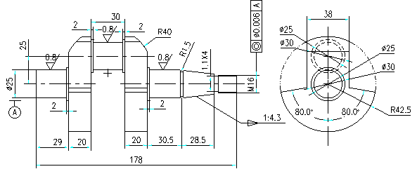
The drawings of the crankshaft are shown in Figure 1. Through the analysis of the drawings, it can be seen that most of the crankshafts are symmetrical, which brings great convenience to modeling. UG's mirroring function can be used to greatly reduce the workload of 3D modeling.
Its main modeling process includes the following steps:
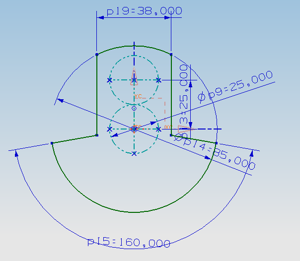
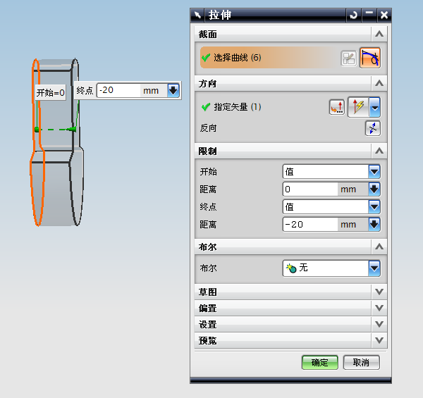
a) draw the outline of the sector in the sketch (as shown in Figure 2), Then by using the stretching function of the UG modeling module, the sketch is generated to generate a fan-shaped part of the entity (as shown in Figure 3);
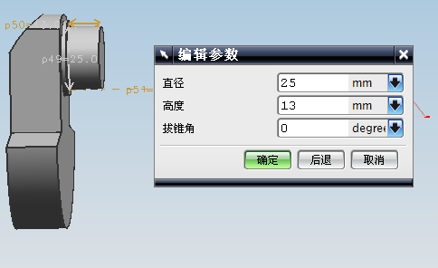
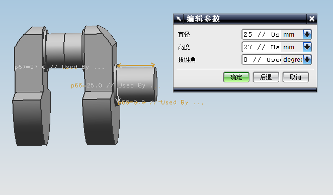
b) Reuse the boss function of the UG modeling module (shown in Figure 4);
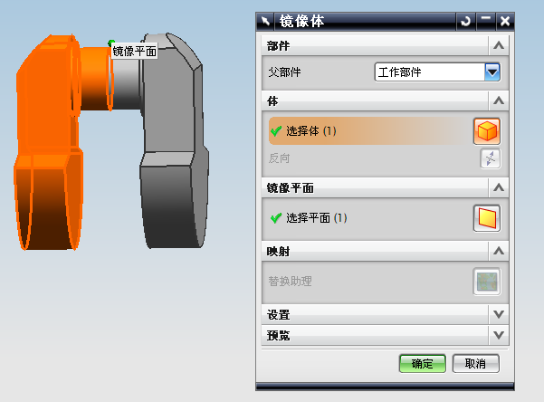
c) Mirror the entities generated in steps a) and b) using the UG mirroring function;
d) Use the UG modeling module to generate the right-end circular truncated cone part, and then use the same method to generate the right-end circular truncated cone part;
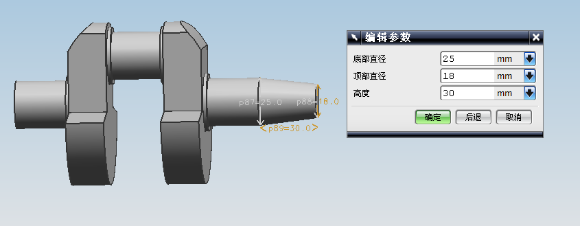
e) Generate a cone-shaped body, and the cylindrical body of the thread portion is also generated using the boss function;
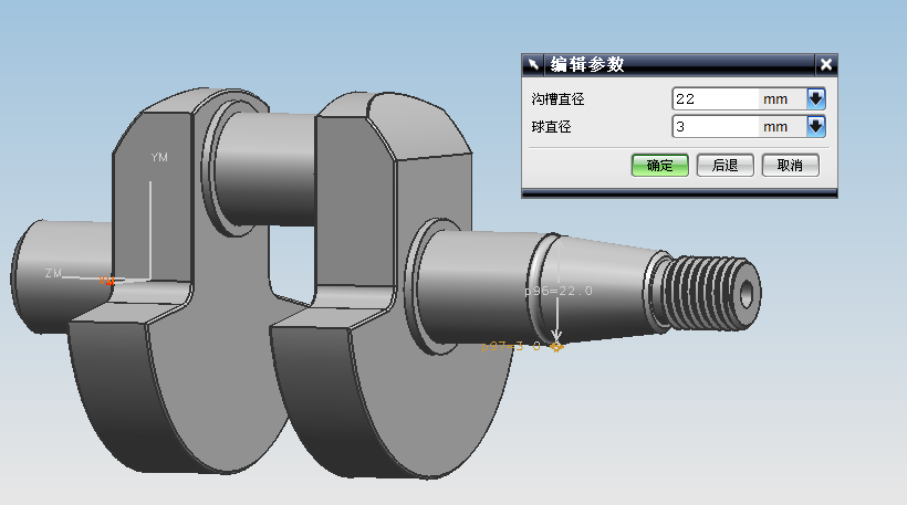
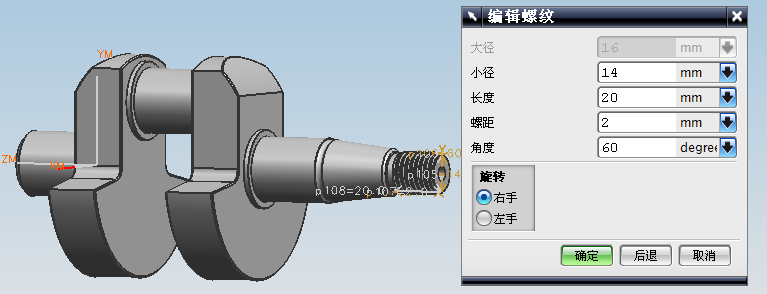
f) Generate relief groove and threads;
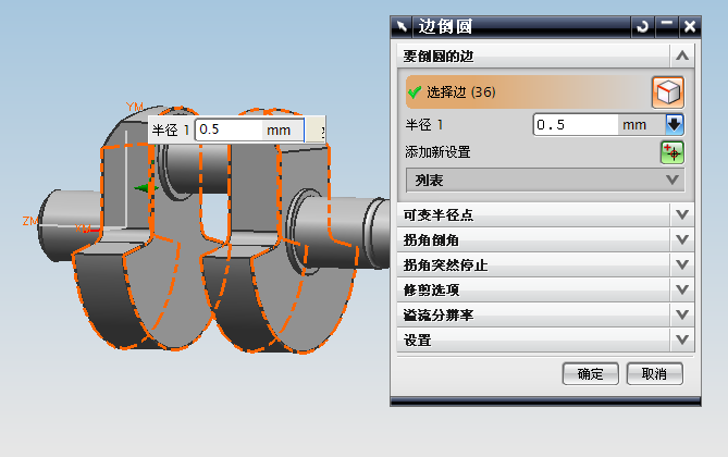
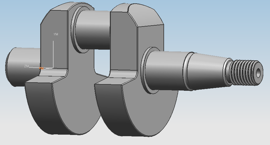
g) Perform detailed processing: rounding, chamfering, etc. to complete the modeling.
2. Crankshaft CNC simulation
NC simulation crankshaft includes the following steps:
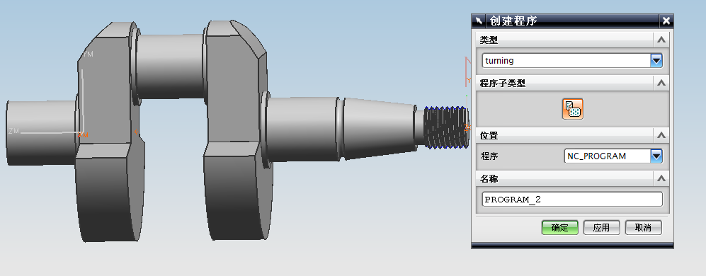
A. Create a program (as shown in Figure 12):
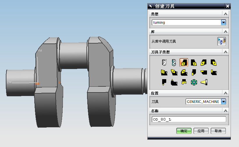
B. Creating tools: The machining of the crankshaft requires a total of 4 tools for roughing, finishing, retracting, and threading.
The process of creating a tool is shown in Figure 13.
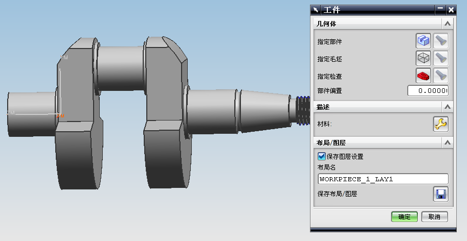
C. Create geometry: Set up the blank, including the size of the blank, the mounting position of the blank, and so on.
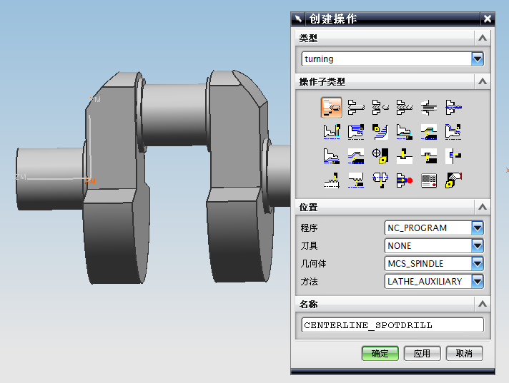
D. Create operation: Select the type of cutting and set the cutting parameters.
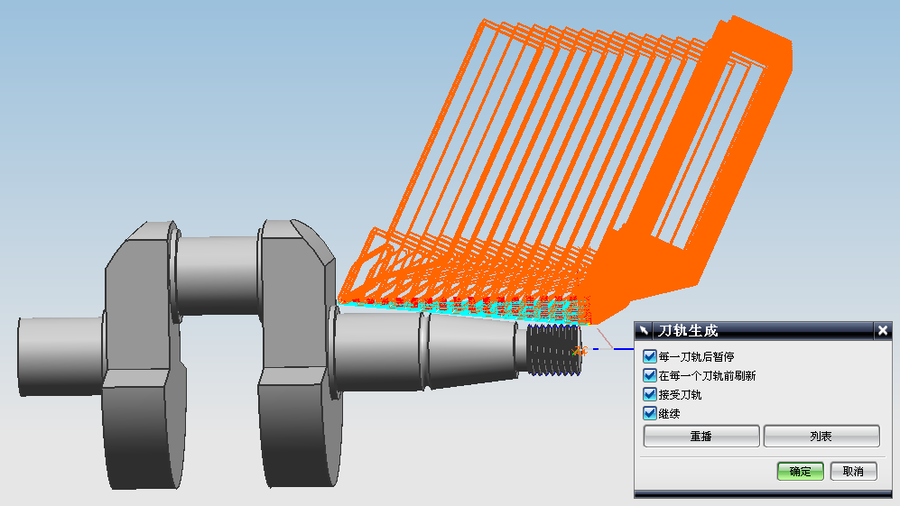
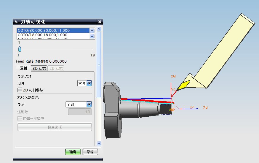
E. After completing the above settings, you can generate the NC tool path, and you can also perform dynamic simulation.
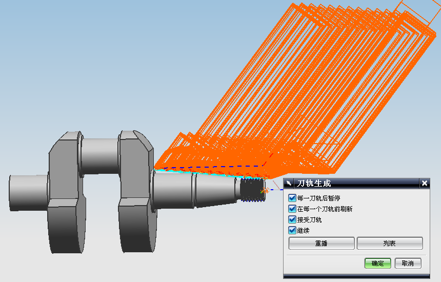
F. Check and analyze the tool path. If there is any error, you can edit the tool path. After the confirmation, you can enter the post-processing stage to generate the CNC machining NC code.
G. The following are some of the generated NC codes (only the codes for roughing and finishing are listed due to space limitations):
a) Roughing:
N0010 G94 G90 G20
N0020 G50 X0.0 Z0.0
:0030 T00 H00 M06
N0040 G94 G00 X15.5 Z3.9747
N0050 G97 S0 M03
N0060 G95 G01 Z2.7747 F.3
N0070 Z-.2253 F.5
N0080 X16. Z-76.5
N0090 X16.8485 Z-75.6515 F1.
N0100 G94 G00 X17.
N0110 Z3.9747
N0120 X15.5
N0130 G95 G01 Z2.7747 F.3
N0140 Z-75.4456
N0150 X15.5959 Z-76.5
N0160 X16.
N0170 X16.8485 Z-75.6515 F1.
N0180 G94 G00 Z4.1832
N0190 X15.
N0200 G95 G01 Z2.9832 F.3
N0210 Z-.0168
N0220 X15.5 Z-75.4456
N0230 X16.3485 Z-74.597 F1.
N0240 G94 G00 X16.5
N0250 Z4.1832
N0260 X15.
N0270 G95 G01 Z2.9832 F.3
N0280 Z-69.9456
N0290 X15.5 Z-75.4456
N0300 X16.3485 Z-74.597 F1.
N0310 G94 G00 Z4.2
N0320 X14.5
N0330 G95 G01 Z3. F.3
N0340 Z0.0
N0350 X15. Z-69.9456
N0360 X15.8485 Z-69.097 F1.
N0370 G94 G00 X16.
N0380 Z4.2
N0390 X14.5
N0400 G95 G01 Z3. F.3
N0410 Z-64.4456
N0420 X15. Z-69.9456
N0430 X15.8485 Z-69.097 F1.
N0440 G94 G00 Z4.2
N0450 X14.
N0460 G95 G01 Z3. F.3
N0470 Z0.0
N0480 X14.5 Z-64.4456
N0490 X15.3485 Z-63.597 F1.
N0500 G94 G00 X15.5
N0510 Z4.2
N0520 X14.
N0530 G95 G01 Z3. F.3
N0540 Z-58.9456
N0550 X14.5 Z-64.4456
N0560 X15.3485 Z-63.597 F1.
N0570 G94 G00 Z4.2
N0580 X13.5
N0590 G95 G01 Z3. F.3
N0600 Z0.0
N0610 X14. Z-58.9456
N0620 X14.8485 Z-58.097 F1.
N0630 G94 G00 X15.
N0640 Z4.2
N0650 X13.5
N0660 G95 G01 Z3. F.3
N0670 Z-53.4456
N0680 X14. Z-58.9456
N0690 X14.8485 Z-58.097 F1.
N0700 G94 G00 Z4.2
N0710 X13.
The crankshaft is the central part of the internal combustion engine and is the heart of the engine. If its function cannot be accurately performed, the horsepower of the engine cannot be normally used. The relative angles of the crankshaft must be correct, otherwise the precise timing of the ignition timing and valve timing will not be able to operate exactly one cylinder after another. If there is a problem with this sequence, one can imagine that the result is a detonation.
The crankshaft is one of the most difficult to process workpieces. It is extremely asymmetric, long and slender, and the materials used are also poor in processability, but the quality is very strict and the manufacturing requirements are very high. The use of the currently widely used three-dimensional software platform, through continuous improvement of its three-dimensional solid modeling, can greatly improve the design accuracy of the crankshaft, and thus also laid the foundation for improving its performance.
Keywords: crankshaft, UG, 3D modeling, automatic programming, CNC machining
1.2.1 crankshaft CNC machining requirements:
Crankshaft, eccentric shaft, eccentric sleeve, etc. are eccentric rotary parts. Its main profile, including the main journal and both ends of the bearing journal are processed on the lathe, and their common features in the processing technology are:
When machining the rotor journal, the axis must be adjusted to coincide with the center of rotation of the lathe spindle. Therefore, the most important process requirements in mass production must be the use of reasonable fixtures and clamping methods to ensure the accuracy of the eccentricity.
The second is that both the center hole and the eccentric center hole at both ends are used as the reference for machining.
At present, according to the specific requirements of the crankshaft's own precision requirements, batch size, and the level of existing processing equipment, a variety of processing methods and processing methods can be selected. For example, the main journal can use both traditional turning techniques and advanced machining techniques such as lathes and high-speed milling to improve machining efficiency and machining quality.
2.2.2 Overall Design Ideas
Parametric design is used in the three-dimensional modeling of the crankshaft to adjust the local structure and size of the crankshaft at any time. Engineers can use the feature values, arrays, and other feature editing functions provided by the UG to provide a parametric design of the crankshaft based on features. The general idea of using the UG modeling module for three-dimensional modeling of the crankshaft can be summarized as follows:
a) Use the dimensional constraints and geometric constraints of the sketch to draw a reasonable crooked interface and the notch and cross section of the curve.The entire crank curve solid model is then obtained through stretch modeling and material removal operations.
b) Reuse the feature operation to copy another crank entity. Try not to use the "geometric transformation" operation instruction.
c) Use basic voxel features provided by UG to complete basic entities such as bolster bearings, keyways, grooves, and threads.
d) Perform a boolean sum on all the above entities to obtain a three-dimensional solid model of the crankshaft entity.
e) Refine the crankshaft body by chamfering, rounding and drilling the center hole of the end face of the crankshaft.
f) Based on the above-mentioned modeling, a multi-turn crankshaft entity is constructed by performing a copy operation and a local modification on the crankshaft.
1. Three-dimensional modeling of the crankshaft
The drawings of the crankshaft are shown in Figure 1. Through the analysis of the drawings, it can be seen that most of the crankshafts are symmetrical, which brings great convenience to modeling. UG's mirroring function can be used to greatly reduce the workload of 3D modeling.
Its main modeling process includes the following steps:
a) draw the outline of the sector in the sketch (as shown in Figure 2), Then by using the stretching function of the UG modeling module, the sketch is generated to generate a fan-shaped part of the entity (as shown in Figure 3);
b) Reuse the boss function of the UG modeling module (shown in Figure 4);
c) Mirror the entities generated in steps a) and b) using the UG mirroring function;
d) Use the UG modeling module to generate the right-end circular truncated cone part, and then use the same method to generate the right-end circular truncated cone part;
e) Generate a cone-shaped body, and the cylindrical body of the thread portion is also generated using the boss function;
f) Generate relief groove and threads;
g) Perform detailed processing: rounding, chamfering, etc. to complete the modeling.
2. Crankshaft CNC simulation
NC simulation crankshaft includes the following steps:
A. Create a program (as shown in Figure 12):
B. Creating tools: The machining of the crankshaft requires a total of 4 tools for roughing, finishing, retracting, and threading.
The process of creating a tool is shown in Figure 13.
C. Create geometry: Set up the blank, including the size of the blank, the mounting position of the blank, and so on.
D. Create operation: Select the type of cutting and set the cutting parameters.
E. After completing the above settings, you can generate the NC tool path, and you can also perform dynamic simulation.
F. Check and analyze the tool path. If there is any error, you can edit the tool path. After the confirmation, you can enter the post-processing stage to generate the CNC machining NC code.
G. The following are some of the generated NC codes (only the codes for roughing and finishing are listed due to space limitations):
a) Roughing:
N0010 G94 G90 G20
N0020 G50 X0.0 Z0.0
:0030 T00 H00 M06
N0040 G94 G00 X15.5 Z3.9747
N0050 G97 S0 M03
N0060 G95 G01 Z2.7747 F.3
N0070 Z-.2253 F.5
N0080 X16. Z-76.5
N0090 X16.8485 Z-75.6515 F1.
N0100 G94 G00 X17.
N0110 Z3.9747
N0120 X15.5
N0130 G95 G01 Z2.7747 F.3
N0140 Z-75.4456
N0150 X15.5959 Z-76.5
N0160 X16.
N0170 X16.8485 Z-75.6515 F1.
N0180 G94 G00 Z4.1832
N0190 X15.
N0200 G95 G01 Z2.9832 F.3
N0210 Z-.0168
N0220 X15.5 Z-75.4456
N0230 X16.3485 Z-74.597 F1.
N0240 G94 G00 X16.5
N0250 Z4.1832
N0260 X15.
N0270 G95 G01 Z2.9832 F.3
N0280 Z-69.9456
N0290 X15.5 Z-75.4456
N0300 X16.3485 Z-74.597 F1.
N0310 G94 G00 Z4.2
N0320 X14.5
N0330 G95 G01 Z3. F.3
N0340 Z0.0
N0350 X15. Z-69.9456
N0360 X15.8485 Z-69.097 F1.
N0370 G94 G00 X16.
N0380 Z4.2
N0390 X14.5
N0400 G95 G01 Z3. F.3
N0410 Z-64.4456
N0420 X15. Z-69.9456
N0430 X15.8485 Z-69.097 F1.
N0440 G94 G00 Z4.2
N0450 X14.
N0460 G95 G01 Z3. F.3
N0470 Z0.0
N0480 X14.5 Z-64.4456
N0490 X15.3485 Z-63.597 F1.
N0500 G94 G00 X15.5
N0510 Z4.2
N0520 X14.
N0530 G95 G01 Z3. F.3
N0540 Z-58.9456
N0550 X14.5 Z-64.4456
N0560 X15.3485 Z-63.597 F1.
N0570 G94 G00 Z4.2
N0580 X13.5
N0590 G95 G01 Z3. F.3
N0600 Z0.0
N0610 X14. Z-58.9456
N0620 X14.8485 Z-58.097 F1.
N0630 G94 G00 X15.
N0640 Z4.2
N0650 X13.5
N0660 G95 G01 Z3. F.3
N0670 Z-53.4456
N0680 X14. Z-58.9456
N0690 X14.8485 Z-58.097 F1.
N0700 G94 G00 Z4.2
N0710 X13.


