4 Kinds Of CNC Machining Technology Ingenious Utilized
One, bottom slitter way
1. Outer protruding parts processing
As shown in Fig. 1, when machining outside open outer protruding, the "plane profile processing" method can be used for processing. Generally, the tool is selected from the point P1 outside the blank (A'B'C'D') material, so that the vertical knife can be used, and the straight cutting method can be used. If you choose to cut a knife from a certain point on the surface of the solid material, you can only use the spiral knife method or linear progressive method. Otherwise, pre-drilling (pre-drilling of a small hole with a bit, then vertical cutting with a vertical cutter in the pre-drilling hole for planar cutting) is required. If you do not understand this point, directly under the physical material on the knife, put the cutter used as a drill, easy to damage the tool.
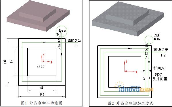
Assume that the size of the blank A'B'C'D' is 100×100 and the size of the boss is 60×60. Using the φ24 end mill, the manual programming of the vertical lower knife is:
G00Z50
X42Y65 (point P 1 outside the entity)
Z-2 (perpendicular to the lower blade, depth of cut 2mm) G01Y-42F300 (linear cut)
......
If a smaller milling cutter, for example an end mill with a Φ 16 is used, multi-tool machining (that is, multi-row machining) is required.As shown in Fig. 2, an "from outside to inside" cut-out method should be adopted for such an outsole. This not only guarantees the removal of the tool from outside the entity, but also makes it easy to reserve the finishing allowance. For flat knives, the line spacing (row-to-line distance) for rough cutting can be between 0.7% and 0.8% of the cutter diameter.
2. The inner cavity machining
When machining recessed cavities, it is inevitable to cut a knife from the solid material.
If you are machining a part on a CNC machining center, you can use the center drill to pre-drill a smaller hole and then use the "Plane area machining" method for machining.
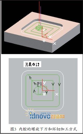
If it is processed on an ordinary CNC milling machine, there is no need to pre-drill the hole. Use the “helical lower knife mode” to place the knife and then perform the plane machining (saving tool change time). The manual programming of the spiral cutting mode is:
G00Z50
X-6Y-6 (lumen machining the knife points on the XY plane P 1)
Z10 (Z direction relative to slow the blade height of the point)
G01Z1F100 (starting point of spiral knife in Z direction)
G91G03I0J6Z-1L3 (helical lower knife, cutting depth 2mm in place)
G90 G03I-3J0 (This sentence can not be omitted, otherwise it will leave some unprocessed clean marks on the bottom surface of the workpiece)
G01Y6F300 (Initial "planar cavity machining" from inside to outside)
......
In addition to the outer spiral manner under the knife, the knife may also be used straight inclined manner,
Or a straight knife cutting mode gradually.
2, The clever use of finish allowance
Finish allowance in machinery manufacturing technology, and automatic programming software finish allowance is different.
The former refers to the margin that should be removed during the processing, and the latter refers to the margin left after the completion of the processing.
For example, if the finished size of the inner hole is Φ 800+0.2, if the current machining is the final finishing, the “remaining allowance” in the automatic programming should be set to “0”; if this processing still needs to remain unilaterally For 0.1mm for finishing, the "Mask allowance" should be set to "0.1" when programming.
We can use it cleverly to solve the middle size calculation problem of asymmetrical tolerances. In manual programming, it is usually programmed with “intermediate dimensions” to ensure that the actual dimensions of the machined part are within the required dimensional tolerances. For asymmetrical tolerances, it is often cumbersome to calculate the median size. In automatic programming, this problem can be easily solved by setting the machining allowance.
As shown in Fig.7a, the lower deviation is the basic deviation 0 and the upper deviation is +0.2. Therefore, only the machining allowance is set to 0.05, then the programming software will automatically calculate the trajectory according to the middle size of 60.1mm.
The parts shown in Fig. 7b have an upper deviation of 0, a lower deviation of -0.2, and a machining allowance of -0.05, so that the programming software can automatically calculate the trajectory at an intermediate size of 59.9 mm.
In addition, the previously mentioned outer contour adopts the “from the outside to the inside” and the inner contour adopts the “from the inside to the outside” approach to cutting. It is also convenient to use the “remaining allowance” setting to complete the rough finish machining of the parts.
3, corner transition mode
The trajectory design of CAXA automatic programming software needs to set "corner transition mode", which is the processing mode when corners are encountered in the cutting process. The CNC will automatically recognize the corners of the inside corners. For the inside corner machining, the center trajectory of the tool at the corners must pass through the intersection point P of the contour track equidistant line, as shown in Figure 8.
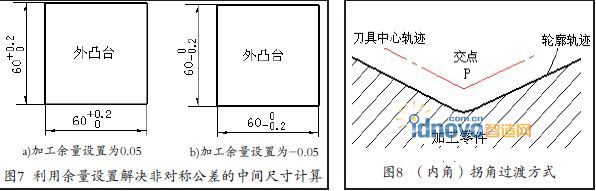
Figure 9 shows two transitions when machining an outside corner.
Figure 9a is a sharp corner transition, that is, at the corner where a contour is processed to another contour, The center trajectory of the tool is the intersection of two equidistant straight lines (the intersection of 1P and 2P with the tool radius as the distance).
Fig. 9b shows the circular arc transition mode. That is, at the corner where one contour is processed to another contour, the tool center trajectory is an arc (an arc of 1 to 2 in the diagram).The starting point is the ending point of the previous curve, the ending point is the starting point of the following curve, and the radius is equal to the tool radius.
From the aspect of cutting technology, in the processing of semi-closed or closed inner and outer contours, the standstill in processing should be avoided as much as possible.Because the "part-tool-machine tool" process system is temporarily in a state of dynamic equilibrium and elastic deformation during machining, if the feed suddenly stops, the cutting force will be significantly reduced.
The balance of the original process system will be lost and the tool will leave scratches or dents at the standstill, affecting the machining quality of the part surface.
Obviously, from the point of view of craftsmanship, corner transitions should be selected as far as possible. However, when the sharp corner transitions, the distance traveled by the tool is longer than the arc transition, especially when the angle α of the part is smaller, the intersection of the tool center trajectory at the corner becomes farther, which affects the machining efficiency. Therefore, the corner transition selection principle should be: when roughing is generally selected "arc transition", finishing (especially when the corner requires a sharp angle and the surface quality requirements are higher), select "sharp corner transition."
There are also sharp-point transitions and arc transitions in manual programming. The instruction codes corresponding to the sharp corner transition are G451 (SIEMENS system) and G61 (FANUC system), and the codes corresponding to arc transition are G450 (SIEMENS system) and G64 (FANUC system).
1. Outer protruding parts processing
As shown in Fig. 1, when machining outside open outer protruding, the "plane profile processing" method can be used for processing. Generally, the tool is selected from the point P1 outside the blank (A'B'C'D') material, so that the vertical knife can be used, and the straight cutting method can be used. If you choose to cut a knife from a certain point on the surface of the solid material, you can only use the spiral knife method or linear progressive method. Otherwise, pre-drilling (pre-drilling of a small hole with a bit, then vertical cutting with a vertical cutter in the pre-drilling hole for planar cutting) is required. If you do not understand this point, directly under the physical material on the knife, put the cutter used as a drill, easy to damage the tool.
Assume that the size of the blank A'B'C'D' is 100×100 and the size of the boss is 60×60. Using the φ24 end mill, the manual programming of the vertical lower knife is:
G00Z50
X42Y65 (point P 1 outside the entity)
Z-2 (perpendicular to the lower blade, depth of cut 2mm) G01Y-42F300 (linear cut)
......
If a smaller milling cutter, for example an end mill with a Φ 16 is used, multi-tool machining (that is, multi-row machining) is required.As shown in Fig. 2, an "from outside to inside" cut-out method should be adopted for such an outsole. This not only guarantees the removal of the tool from outside the entity, but also makes it easy to reserve the finishing allowance. For flat knives, the line spacing (row-to-line distance) for rough cutting can be between 0.7% and 0.8% of the cutter diameter.
2. The inner cavity machining
When machining recessed cavities, it is inevitable to cut a knife from the solid material.
If you are machining a part on a CNC machining center, you can use the center drill to pre-drill a smaller hole and then use the "Plane area machining" method for machining.
If it is processed on an ordinary CNC milling machine, there is no need to pre-drill the hole. Use the “helical lower knife mode” to place the knife and then perform the plane machining (saving tool change time). The manual programming of the spiral cutting mode is:
G00Z50
X-6Y-6 (lumen machining the knife points on the XY plane P 1)
Z10 (Z direction relative to slow the blade height of the point)
G01Z1F100 (starting point of spiral knife in Z direction)
G91G03I0J6Z-1L3 (helical lower knife, cutting depth 2mm in place)
G90 G03I-3J0 (This sentence can not be omitted, otherwise it will leave some unprocessed clean marks on the bottom surface of the workpiece)
G01Y6F300 (Initial "planar cavity machining" from inside to outside)
......
In addition to the outer spiral manner under the knife, the knife may also be used straight inclined manner,
Or a straight knife cutting mode gradually.
2, The clever use of finish allowance
Finish allowance in machinery manufacturing technology, and automatic programming software finish allowance is different.
The former refers to the margin that should be removed during the processing, and the latter refers to the margin left after the completion of the processing.
For example, if the finished size of the inner hole is Φ 800+0.2, if the current machining is the final finishing, the “remaining allowance” in the automatic programming should be set to “0”; if this processing still needs to remain unilaterally For 0.1mm for finishing, the "Mask allowance" should be set to "0.1" when programming.
We can use it cleverly to solve the middle size calculation problem of asymmetrical tolerances. In manual programming, it is usually programmed with “intermediate dimensions” to ensure that the actual dimensions of the machined part are within the required dimensional tolerances. For asymmetrical tolerances, it is often cumbersome to calculate the median size. In automatic programming, this problem can be easily solved by setting the machining allowance.
As shown in Fig.7a, the lower deviation is the basic deviation 0 and the upper deviation is +0.2. Therefore, only the machining allowance is set to 0.05, then the programming software will automatically calculate the trajectory according to the middle size of 60.1mm.
The parts shown in Fig. 7b have an upper deviation of 0, a lower deviation of -0.2, and a machining allowance of -0.05, so that the programming software can automatically calculate the trajectory at an intermediate size of 59.9 mm.
In addition, the previously mentioned outer contour adopts the “from the outside to the inside” and the inner contour adopts the “from the inside to the outside” approach to cutting. It is also convenient to use the “remaining allowance” setting to complete the rough finish machining of the parts.
3, corner transition mode
The trajectory design of CAXA automatic programming software needs to set "corner transition mode", which is the processing mode when corners are encountered in the cutting process. The CNC will automatically recognize the corners of the inside corners. For the inside corner machining, the center trajectory of the tool at the corners must pass through the intersection point P of the contour track equidistant line, as shown in Figure 8.
Figure 9 shows two transitions when machining an outside corner.
Figure 9a is a sharp corner transition, that is, at the corner where a contour is processed to another contour, The center trajectory of the tool is the intersection of two equidistant straight lines (the intersection of 1P and 2P with the tool radius as the distance).
Fig. 9b shows the circular arc transition mode. That is, at the corner where one contour is processed to another contour, the tool center trajectory is an arc (an arc of 1 to 2 in the diagram).The starting point is the ending point of the previous curve, the ending point is the starting point of the following curve, and the radius is equal to the tool radius.
From the aspect of cutting technology, in the processing of semi-closed or closed inner and outer contours, the standstill in processing should be avoided as much as possible.Because the "part-tool-machine tool" process system is temporarily in a state of dynamic equilibrium and elastic deformation during machining, if the feed suddenly stops, the cutting force will be significantly reduced.
The balance of the original process system will be lost and the tool will leave scratches or dents at the standstill, affecting the machining quality of the part surface.
Obviously, from the point of view of craftsmanship, corner transitions should be selected as far as possible. However, when the sharp corner transitions, the distance traveled by the tool is longer than the arc transition, especially when the angle α of the part is smaller, the intersection of the tool center trajectory at the corner becomes farther, which affects the machining efficiency. Therefore, the corner transition selection principle should be: when roughing is generally selected "arc transition", finishing (especially when the corner requires a sharp angle and the surface quality requirements are higher), select "sharp corner transition."
There are also sharp-point transitions and arc transitions in manual programming. The instruction codes corresponding to the sharp corner transition are G451 (SIEMENS system) and G61 (FANUC system), and the codes corresponding to arc transition are G450 (SIEMENS system) and G64 (FANUC system).


