CNC Machined Glass Surface Technology
CNC processing glass process
Board cut - CNC - cleaning inspection - strengthening - prepress inspection - silk screen - AF - packaging
CNC process: Using precision engraving machine, grinding glass material with masonry wheel bar, forming holes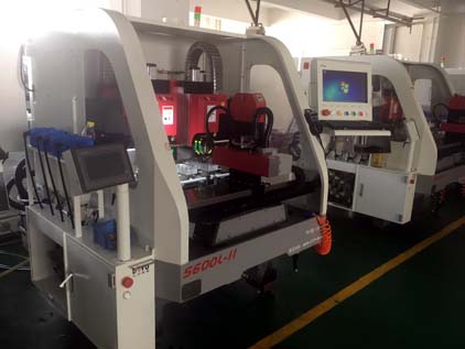
1. Rotary hole: The tip spiral spirals deeper until it penetrates
2. Coarse reaming: Lateral rough machining by turning holes
3. Finishing: Using a fine sand groove to refine the contour of the hole and machining the inverted edge shape
1.Open rough: Use coarse sand to remove all corners
2. Finishing: Fine-grinding the product using fine sand grooves and machining the edges
Introduction of glass cutting fluid
Application
Suitable for glass, resin glass, optical glass, plate glass, camera lenses, eyeglass lenses, sapphire glass, magnets, quartz optical products, high-grade marble, gourmet granite, ceramic wafers, cutting of CRT glass for television video recorders, grinding process rust-proof cooling.
Performance characteristics
1. Good cleaning and penetrating performance, which can prevent passivation of tool grinding tools, have good self-sharpening effect on grinding tools, increase cutting force of diamond tools, prolong the service life of diamond tools, and shorten the processing time of workpieces;
2. Outstanding lubricating performance, obviously reduce the noise generated when cutting the workpiece, avoid the spark phenomenon when cutting the workpiece, reduce the occurrence of abrasive scratches, obviously improve the surface quality of the processed workpiece, and greatly improve the finish of the workpiece.
3 can effectively inhibit the corrosive hazards of various factors on the glass;
4. Good non-foaming performance, excellent debris sedimentation function;
5. Good anti-rust performance, anti-corrosive performance, good product stability, long service life;
6. Water-based transparent formula, working fluid with high transparency and cleanliness
7. Water-based environmental protection products, unique washing and cleaning performance, miscellaneous oil floats on the coolant and is easy to clean;
8. The performance is mild, the machine tool paint is not easy to fall off.
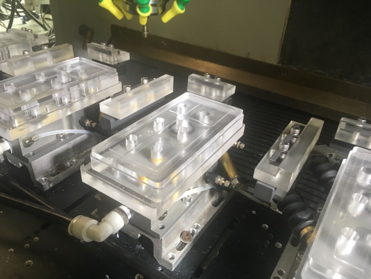
Base fixture
Fixture surface should be smooth without burr, right angle should be chamfered to prevent scratching the product
Adsorption true negative air pressure must be> -0.7 bar (- 0.07 ± 0.02MPa)
The angle should be checked every shift for wear and timely replacement
2. Abnormal Analysis of Glass Processing and Countermeasures
1.1 Common bad types: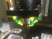
1, Edge breakage;
2, hole sand collapse
3, bright border
4, scratch
5, R angular deformation
6, hole deformation
7, Slot avalanche
8, burning edge
2.1 Bad Edge breakage
Edge breakage disadvantages are more than 0.05mm in height and cannot be repaired.
Defects of sand collapse is less than 0.03mm in height and can be repaired.
Reasons and Countermeasures for Bad Edge Breakage
Shape edge, slot edge, Edge breakage reason and processing method of unfixed position
Grinding wheel bar coarse sand wear: change grinding wheel bar processing depth
rough machining speed is too fast: reducing machining feed speed
Less cutting fluid flow, cooling effect is not enough: spindle speed decreases, adjust cutting fluid flow.
Rough machining Reserved too little: change the processing program, increase the reserve
Downhole knife point, or Lift the knife point, causes and treatment of collapse at fixed locations
Wheel rod tip wear: Replace the new wheel bar
Grinding wheel oversize tolerance: Check the size of the grinding wheel bar, the upper limit size cannot be used
Collision with glass when cutting or lifting: Simulate machining, check the machining path, and then modify the machining program
The feeding speed of the hole processing is too fast and the spiral depth is too much: Decrease hole spiral processing speed and spiral depth
2.4, Bad border bad phenomenon:
The normal straightening of the glass side is a frosted matte surface, and it will be shiny when it is not processed.
The bad reason for bright border:
1>Product location bias
Workers' practices are not standardized
Wear angle
2> Positioning during product processing
Negative air pressure is not enough, the glass can not suck
The product size is too small, resulting in poor glass absorption
The processing speed is too fast or the cutting amount is too large and the machining resistance is too high
Bad bright border countermeasures
Operator's technical training
Check/Replace New Corner
Negative pressure check confirm
Modify processing procedures to reduce processing speed and cutting amount
Pad of paper, to increase the friction
Improved base, increasing adsorption area
Bad scratches
The glass surface point, line, area shaped like scratches
Measures bad scratch
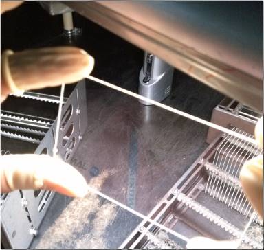
One-handed principle, the principle of holding both sides of the glass
Cleaning base movements and requirements
Check the corner of the base and polish it with fine sandpaper to remove burrs
Inspect the scratches after the incoming and cleaning materials are inspected, verify and eliminate the location of the scratches
Change the base design to reduce the contact area of the base
Measures bad scratch
The large-size glass base can be inhaled by the surrounding air ducts, and the hollowed out base design in the middle can well reduce the contact area between the glass and the base and reduce scratches.
2.5, R corner distortion bad phenomenon
R-angle deformation, knife marks mainly appear in the contour / groove of the knife cutter position
Caused by R-Angle Deformation, Causes and Countermeasures
After the wheel bar wears, the fine diameter and the thick diameter do not match the actual program settings. After tool compensation adjustment, the arc and tangent cannot be completely tangent to produce a tool mark.
Change the path of the knife and knife to a small angle and smooth the intersection to avoid the generation of knife marks
2.6 Causes and Countermeasures of Poor Inner Deformation
X, Y axis bearing wear
Equipment maintenance
program
Graphical distortion
Program output processing program calculation error
There are too many decimal places for the diameter of the circle and the diameter of the tool, and the reserved amount is set.
Caused the calculation of coordinate values to be too large, causing calculation errors
Using MCU Software to Analyze Point Data
The processing value is set to an integer value of 0.01
2.7 Bad phenomena of hole and corner collapse:
The collapse of the gap is a gap in the straight-up position, which is different from that in the collapse side.
Poor slot and corner collapse defects:
Breaking of the cutting residue causes a large gap, and the larger the remaining material area, the larger the resulting gap will be.
Poor slot and corner collapse defects countermeasures:
Reduce speed and reduce fractures
Increase the amount of fracture opening reserve, covering the collapse
3. Common parameters of CNC machining
Processing sequence:
Shape rough finish - Shape finish - Turn hole processing - Hole rough finish- Hole fine machining
Shape roughing - tool parameter items:
Make sure the tool selection is correct. The type of tool is generally a universal flat tool. The diameter of the tool refers to the diameter of the grinding wheel.
Set the processing speed, the processing speed is divided into "feed rate", "lower knife speed" and "lifting knife speed".
Feed rate: refers to the normal processing walking speed. The setting range is usually 1000-1100
Upper knife speed: The tool speed from the safe height to the machining depth before the normal machining starts. Setting range 3000-5000
Lifting knife speed: Refers to the tool lifting speed from the machining depth to the safe height, after the normal machining is completed. Setting range 3000-5000
3. Set the spindle speed. The spindle speed usually uses the default speed of the machine, so usually it does not need to be set. It must be set only when it needs the program to control the number of revolutions. The setting range is 35000-45000 (according to the actual demand).
Roughing - Milling Parameters:
Confirm the height and depth settings. The main settings are “reference height” and “depth”.The reference height, also known as the safe altitude, refers to the height of the tool when the tool's idle stroke moves. To avoid the tool hitting the workpiece when switching the lower knife point movement, usually set the range of 2.0-5.0.
Depth refers to the machining depth during normal machining. The setting value is usually negative. According to the position of the grinding wheel rod machining size.
Set correction mode and direction
The correction mode usually uses the “computer” mode and the “both” mode. When the “computer” mode is set, The tool compensation on the machine tool does not take effect. When setting the "both" mode, the tool compensation on the machine can take effect.
The correction direction is divided into "left" and "right"; usually, the "left" is set for down milling and the "right" is set for up milling. Set the XY reservation amount, as the name implies, that is the reservation of the edge processing profile, When set to a positive number, the external dimensions increase. When set to a negative value, the external dimensions will decrease; the roughing must set a reserve amount, usually setting range 0.1-0.15.
Shape Finishing - Tool Parameter Items:
The finishing tool uses a fine sand refining groove with a wheel bar. Create a new tool in the tool magazine and the set diameter (groove diameter)
The feed rate for finishing is usually set to 700-900.
Other settings are the same as rough settings
Board cut - CNC - cleaning inspection - strengthening - prepress inspection - silk screen - AF - packaging
CNC process: Using precision engraving machine, grinding glass material with masonry wheel bar, forming holes
1. Rotary hole: The tip spiral spirals deeper until it penetrates
2. Coarse reaming: Lateral rough machining by turning holes
3. Finishing: Using a fine sand groove to refine the contour of the hole and machining the inverted edge shape
1.Open rough: Use coarse sand to remove all corners
2. Finishing: Fine-grinding the product using fine sand grooves and machining the edges
Introduction of glass cutting fluid
Application
Suitable for glass, resin glass, optical glass, plate glass, camera lenses, eyeglass lenses, sapphire glass, magnets, quartz optical products, high-grade marble, gourmet granite, ceramic wafers, cutting of CRT glass for television video recorders, grinding process rust-proof cooling.
Performance characteristics
1. Good cleaning and penetrating performance, which can prevent passivation of tool grinding tools, have good self-sharpening effect on grinding tools, increase cutting force of diamond tools, prolong the service life of diamond tools, and shorten the processing time of workpieces;
2. Outstanding lubricating performance, obviously reduce the noise generated when cutting the workpiece, avoid the spark phenomenon when cutting the workpiece, reduce the occurrence of abrasive scratches, obviously improve the surface quality of the processed workpiece, and greatly improve the finish of the workpiece.
3 can effectively inhibit the corrosive hazards of various factors on the glass;
4. Good non-foaming performance, excellent debris sedimentation function;
5. Good anti-rust performance, anti-corrosive performance, good product stability, long service life;
6. Water-based transparent formula, working fluid with high transparency and cleanliness
7. Water-based environmental protection products, unique washing and cleaning performance, miscellaneous oil floats on the coolant and is easy to clean;
8. The performance is mild, the machine tool paint is not easy to fall off.
Base fixture
Fixture surface should be smooth without burr, right angle should be chamfered to prevent scratching the product
Adsorption true negative air pressure must be> -0.7 bar (- 0.07 ± 0.02MPa)
The angle should be checked every shift for wear and timely replacement
2. Abnormal Analysis of Glass Processing and Countermeasures
1.1 Common bad types:
1, Edge breakage;
2, hole sand collapse
3, bright border
4, scratch
5, R angular deformation
6, hole deformation
7, Slot avalanche
8, burning edge
2.1 Bad Edge breakage
Edge breakage disadvantages are more than 0.05mm in height and cannot be repaired.
Defects of sand collapse is less than 0.03mm in height and can be repaired.
Reasons and Countermeasures for Bad Edge Breakage
Shape edge, slot edge, Edge breakage reason and processing method of unfixed position
Grinding wheel bar coarse sand wear: change grinding wheel bar processing depth
rough machining speed is too fast: reducing machining feed speed
Less cutting fluid flow, cooling effect is not enough: spindle speed decreases, adjust cutting fluid flow.
Rough machining Reserved too little: change the processing program, increase the reserve
Downhole knife point, or Lift the knife point, causes and treatment of collapse at fixed locations
Wheel rod tip wear: Replace the new wheel bar
Grinding wheel oversize tolerance: Check the size of the grinding wheel bar, the upper limit size cannot be used
Collision with glass when cutting or lifting: Simulate machining, check the machining path, and then modify the machining program
The feeding speed of the hole processing is too fast and the spiral depth is too much: Decrease hole spiral processing speed and spiral depth
2.4, Bad border bad phenomenon:
The normal straightening of the glass side is a frosted matte surface, and it will be shiny when it is not processed.
The bad reason for bright border:
1>Product location bias
Workers' practices are not standardized
Wear angle
2> Positioning during product processing
Negative air pressure is not enough, the glass can not suck
The product size is too small, resulting in poor glass absorption
The processing speed is too fast or the cutting amount is too large and the machining resistance is too high
Bad bright border countermeasures
Operator's technical training
Check/Replace New Corner
Negative pressure check confirm
Modify processing procedures to reduce processing speed and cutting amount
Pad of paper, to increase the friction
Improved base, increasing adsorption area
Bad scratches
The glass surface point, line, area shaped like scratches
Measures bad scratch
One-handed principle, the principle of holding both sides of the glass
Cleaning base movements and requirements
Check the corner of the base and polish it with fine sandpaper to remove burrs
Inspect the scratches after the incoming and cleaning materials are inspected, verify and eliminate the location of the scratches
Change the base design to reduce the contact area of the base
Measures bad scratch
The large-size glass base can be inhaled by the surrounding air ducts, and the hollowed out base design in the middle can well reduce the contact area between the glass and the base and reduce scratches.
2.5, R corner distortion bad phenomenon
R-angle deformation, knife marks mainly appear in the contour / groove of the knife cutter position
Caused by R-Angle Deformation, Causes and Countermeasures
After the wheel bar wears, the fine diameter and the thick diameter do not match the actual program settings. After tool compensation adjustment, the arc and tangent cannot be completely tangent to produce a tool mark.
Change the path of the knife and knife to a small angle and smooth the intersection to avoid the generation of knife marks
2.6 Causes and Countermeasures of Poor Inner Deformation
X, Y axis bearing wear
Equipment maintenance
program
Graphical distortion
Program output processing program calculation error
There are too many decimal places for the diameter of the circle and the diameter of the tool, and the reserved amount is set.
Caused the calculation of coordinate values to be too large, causing calculation errors
Using MCU Software to Analyze Point Data
The processing value is set to an integer value of 0.01
2.7 Bad phenomena of hole and corner collapse:
The collapse of the gap is a gap in the straight-up position, which is different from that in the collapse side.
Poor slot and corner collapse defects:
Breaking of the cutting residue causes a large gap, and the larger the remaining material area, the larger the resulting gap will be.
Poor slot and corner collapse defects countermeasures:
Reduce speed and reduce fractures
Increase the amount of fracture opening reserve, covering the collapse
3. Common parameters of CNC machining
| terminology | unit | content |
| Feed rate | mm/min | The speed at which the spindle travels in the process, the distance traveled in each minute |
| Plunge cut/lift rate | mm/min | The speed of the walking movement of the spindle Knife lift during processing, the distance traveled within each minute |
| Tool diameter | mm | Cutting diameter (rotary diameter) of a wheel bar or tool |
| Spindle speed | r/min | Spindle revolutions per minute |
| Depth of processing | mm | Cutting depth set by the program, grinding position on the grinding wheel bar |
| Stock to leave | mm | The contour of the processed product is reserved, and the entire machining is reserved for the final cutting. |
Processing sequence:
Shape rough finish - Shape finish - Turn hole processing - Hole rough finish- Hole fine machining
Shape roughing - tool parameter items:
Make sure the tool selection is correct. The type of tool is generally a universal flat tool. The diameter of the tool refers to the diameter of the grinding wheel.
Set the processing speed, the processing speed is divided into "feed rate", "lower knife speed" and "lifting knife speed".
Feed rate: refers to the normal processing walking speed. The setting range is usually 1000-1100
Upper knife speed: The tool speed from the safe height to the machining depth before the normal machining starts. Setting range 3000-5000
Lifting knife speed: Refers to the tool lifting speed from the machining depth to the safe height, after the normal machining is completed. Setting range 3000-5000
3. Set the spindle speed. The spindle speed usually uses the default speed of the machine, so usually it does not need to be set. It must be set only when it needs the program to control the number of revolutions. The setting range is 35000-45000 (according to the actual demand).
Roughing - Milling Parameters:
Confirm the height and depth settings. The main settings are “reference height” and “depth”.The reference height, also known as the safe altitude, refers to the height of the tool when the tool's idle stroke moves. To avoid the tool hitting the workpiece when switching the lower knife point movement, usually set the range of 2.0-5.0.
Depth refers to the machining depth during normal machining. The setting value is usually negative. According to the position of the grinding wheel rod machining size.
Set correction mode and direction
The correction mode usually uses the “computer” mode and the “both” mode. When the “computer” mode is set, The tool compensation on the machine tool does not take effect. When setting the "both" mode, the tool compensation on the machine can take effect.
The correction direction is divided into "left" and "right"; usually, the "left" is set for down milling and the "right" is set for up milling. Set the XY reservation amount, as the name implies, that is the reservation of the edge processing profile, When set to a positive number, the external dimensions increase. When set to a negative value, the external dimensions will decrease; the roughing must set a reserve amount, usually setting range 0.1-0.15.
Shape Finishing - Tool Parameter Items:
The finishing tool uses a fine sand refining groove with a wheel bar. Create a new tool in the tool magazine and the set diameter (groove diameter)
The feed rate for finishing is usually set to 700-900.
Other settings are the same as rough settings


