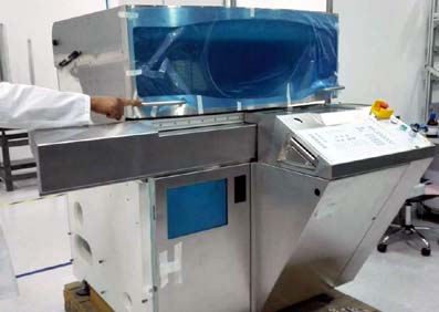
Sheet Metal Processing Technology
Sheet metal processing Encyclopedia of Technical Requirements

In general technical requirements will be noted: "S' X0 R / P% Y
1. Unmarked tolerance requirements IT01、IT0、IT1、IT2~IT18
2. Part of the details of the requirements (such as: grinding burr, etc.)
3. Also note that the surface treatment requires 0 M$ r* D6 ?& |. ]3 {& h+ w) r
4. If there is welding, the treatment of the weld bead will also be required.
Sheet metal technical requirements
Material ** (The name and specification of the material must be specified, and some require the writing of the national standard code);
The thickness and quality of the material shall comply with the national standard. The materials used shall show the performance test report and the manufacturer's certificate.
Material appearance: smooth without rust, no cracking and deformation.
Part size: According to the requirements of drawings and national standards, the important dimensions are zero defects.
Performance: Test assembly and performance meet product requirements.
1. Parts remove oxides.
2. Parts machined surface should not damage the defective parts of the surface scratches, abrasions and the like.
3. remove the burr burr.
4. After conditioning, 28HRC ~ 32HRC.
5. Parts for high-frequency quenching, 350 ~ 370 °C tempering, 40HRC ~ 45HRC.
6. Carburizing depth 0.3mm.7. Perform high temperature aging treatment.
8. Note not form tolerances should meet GB1184-2000.
9. Unmarked dimensional tolerances should be in accordance with GB/T1804-m
10. The casting tolerance zone is symmetrical to the basic size configuration of the blank casting.
11. No injection radius R5.
12. No injection chamfers are 2×45°
15. Assemble the rolling bearing and allow oil heating for hot charging. The temperature of the oil must not exceed 100°C.
16. After the gear is assembled, the contact spot and backlash of the tooth surface shall meet the requirements of GB10095 and GB11365.
17. Seal packings or sealants are permitted when assembling the hydraulic system but should be prevented from entering the system.
18. Access to the assembled parts and components (including purchased parts ) must be qualified by the inspection department before assembly.
19. For fasteners that require tightening torque, a torque wrench must be used and tightened according to the specified tightening torque.
20. When taper pins are assembled, they should be color-checked with the holes. The contact rate should not be less than 60% of the mating length and should be evenly distributed.
21. The flat key and the two sides of the keyway on the shaft should be in uniform contact, and the mating surface must have no clearance.
22. The number of tooth surfaces that the spline assembly contacts at the same time is not less than 2/3. The contact rate must not be less than 50% in the length and height direction of the key teeth.
23. When the flat keys (or splines) are slidingly fitted, the phase fittings move freely and there must be no looseness.
24. The excess adhesive should be removed after bonding.
25. The semi-circular hole of the bearing outer ring and the open type bearing seat and bearing cover must not be stuck.
35. The outer ring of the bearing should be in good contact with the semi-circular holes of the open bearing housing and the bearing cover. When checking with coloring, With the bearing seat symmetrical to the centerline 120°, The contact with the bearing cover should be evenly within 90° symmetrical to the centerline. When using a feeler gauge within the above range, a 0.03mm feeler must not be inserted into 1/3 of the outer ring width.
26. After the bearing outer ring is assembled, it should be evenly contacted with the end face of the locating bearing cap.
27. After the rolling bearing is installed, it should be flexible and stable by hand rotation.
28. The joint surface of the upper and lower bearing bushes should be closely attached and checked with a 0.05mm feeler gauge and cannot be inserted.
29. When fixing the bearing with the positioning pin, it is necessary to ensure that the bearing surface and the end face, The opening of the relevant bearing hole is flush with the end bread. The hinges and drill pins shall not be loosened after entering the page state.
30. The bearing body of the spherical bearing and the bearing seat should be in uniform contact and checked by coloring. The contact should not be less than 70%.
31. The surface of the alloy bearing lining is not allowed to use when it is yellow, and there is no nucleation phenomenon within the specified contact angle, outside the contact angle. The nuclear area shall not be greater than 10% of the total area of the non-contact area.
32. The reference end face of the gear (worm gear) and the shoulder (or the end face of the positioning sleeve) should be attached. checked with a 0.05mm feeler gauge and cannot be inserted. And should ensure the perpendicularity of the reference end face of the gear and the axis.
33. The contact surface between the gear box and the cover should be in good contact.
34. Check and remove any sharp corners, burrs, and foreign objects left on the part before assembly. Ensure that the seal is not scratched when it is installed.


