Stamping Design Of Metal Shell Parts For Automobile Glass Lifter
The shape and size of the car door glass lifter housing parts. As shown in Figure 8.2.1,
The material is 08 steel plate, plate thickness 1.5mm, mass production.
Stamping production, it requires the preparation of a stamping process.
8.2.1 Process analysis of stamping parts
First, you must fully understand the application and technical requirements of the product, and conduct process analysis.
The glass on the car door is lifted or lowered by the lifter.
The assembly diagram of the lifter components is shown in Figure 8.2.2. The stamped part is the outer casing 5 of it. The transmission mechanism of the elevator is housed in the outer casing, and is riveted to the door seat plate by three uniformly distributed small holes φ 3.2mm on the outer casing flange. The drive shaft 6 is mounted on the support portion of the right end hole φ 16.5mm with the clearance of I T11. The brake torsion spring 3, the linkage piece 9 and the spindle 4 are coupled with the pinion 11 to rock the handle 7. The drive shaft transmits power to the pinion, and then drives the large gear 12 to push the door glass up and down.
The stampings are stamped from 1.5mm steel plates to ensure adequate rigidity and strength.
The main mating dimensions of the inner cavity of the housing are φ 16.5 mm, φ 22.3 mm and 16 mm are IT11-IT12.
In order to ensure the coaxiality between the support part and the sleeve after riveting and fixing, the relative position between the three φ 3.2mm small holes and φ 16.5mm is accurate, and the diameter of the small hole center circle is φ 42 ± 0.1mm. T10 level.
This part is a rotating body whose shape is characterized by a flanged cylindrical piece.
The main shape and size can be obtained by a drawing process such as drawing, flanging, punching, and the like.
As the drawing size, the relative values are suitable, and the drawing process is better.
The tolerance requirements for φ 22.3 mm and 16 mm are too high. The radius of the fillet at the bottom and the mouth of the deep drawing piece is also small, so it should be added after the drawing, and the mold with high precision and small gap should be used.
The accuracy of the center circle diameter of the three small holes φ 3.2 mm is 42 ± 0.1mm. According to the technical analysis of the blanking parts, the inner diameter of φ 22.3 mm should be positioned, and the high-precision (IT7 or higher) die should be punched out simultaneously in one process.
Figure 8.2.1 Glass lifter metal casing
Figure 8.2.2 Assembly diagram of the glass lifter housing
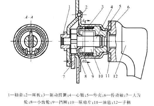
Figure 8.2.3 Forming scheme at the bottom of the casing
a) cut; b) punching; c) punching flanging
The material is 08 steel plate, plate thickness 1.5mm, mass production.
Stamping production, it requires the preparation of a stamping process.
8.2.1 Process analysis of stamping parts
First, you must fully understand the application and technical requirements of the product, and conduct process analysis.
The glass on the car door is lifted or lowered by the lifter.
The assembly diagram of the lifter components is shown in Figure 8.2.2. The stamped part is the outer casing 5 of it. The transmission mechanism of the elevator is housed in the outer casing, and is riveted to the door seat plate by three uniformly distributed small holes φ 3.2mm on the outer casing flange. The drive shaft 6 is mounted on the support portion of the right end hole φ 16.5mm with the clearance of I T11. The brake torsion spring 3, the linkage piece 9 and the spindle 4 are coupled with the pinion 11 to rock the handle 7. The drive shaft transmits power to the pinion, and then drives the large gear 12 to push the door glass up and down.
The stampings are stamped from 1.5mm steel plates to ensure adequate rigidity and strength.
The main mating dimensions of the inner cavity of the housing are φ 16.5 mm, φ 22.3 mm and 16 mm are IT11-IT12.
In order to ensure the coaxiality between the support part and the sleeve after riveting and fixing, the relative position between the three φ 3.2mm small holes and φ 16.5mm is accurate, and the diameter of the small hole center circle is φ 42 ± 0.1mm. T10 level.
This part is a rotating body whose shape is characterized by a flanged cylindrical piece.
The main shape and size can be obtained by a drawing process such as drawing, flanging, punching, and the like.
As the drawing size, the relative values are suitable, and the drawing process is better.
The tolerance requirements for φ 22.3 mm and 16 mm are too high. The radius of the fillet at the bottom and the mouth of the deep drawing piece is also small, so it should be added after the drawing, and the mold with high precision and small gap should be used.
The accuracy of the center circle diameter of the three small holes φ 3.2 mm is 42 ± 0.1mm. According to the technical analysis of the blanking parts, the inner diameter of φ 22.3 mm should be positioned, and the high-precision (IT7 or higher) die should be punched out simultaneously in one process.
Figure 8.2.1 Glass lifter metal casing
Figure 8.2.2 Assembly diagram of the glass lifter housing
1, bushings. 2, seat plate. 3, brake torsion spring. 4, the mandrel. 5, the outer casing. 6, the drive shaft. 7, big gear. 8, pinion. 9, the retaining ring. 10, linkage film.11, linoleum. 12, the handle
8.2.2 Determination of stamping process
one. Analysis and comparison of process plans
The shape of the outer casing indicates that it is a deep drawing piece, so drawing is a basic process.
The three small holes in the flange are completed by a punching process.
The forming of the part φ 16.5 mm (see the right side of Figure 8.2.1) can be done in three ways:
1, can use Step deep drawing, turning to the bottom;
2, after the Step deep drawing can be used, stamping removes the bottom;
3, You can use the method of drawing, Punching bottom hole, and then flanging. (See Figure 8.2.3)
The first method has a higher quality at the bottom of the turning but has a lower productivity. It is not easy to use when the bottom of the part is not high.
The second method requires the bottom fillet radius to be close to zero before stamping to remove the bottom, so an additional shaping process is required and the quality is not easily guaranteed.
The third method, although the quality of the end of the flange is not as good as the first two, but the production efficiency is high, and the material is saved.
Since the tolerance of the housing height dimension of 21 mm is not high, the flanging process can fully guarantee the technical requirements of the parts, so it is reasonable to use the method of deep drawing and then punching and flanging.
Figure 8.2.3 Forming scheme at the bottom of the casing
a) cut; b) punching; c) punching flanging
PREV:Design And Selection Of Mold Parts
NEXT:NONE
NEXT:NONE


